Installation, Wiring,
and Specifications
2--22
Installation, Wiring, and Specifications
DL105 PLC User Manual, 3rd Edition
The F1--130AR, F1--130DR/F1--130DR--CE, and F1--130DR--D models feature
relay outputs. Relays are best for the following applications:
S Loads that require higher currents than the solid-state DL105 outputs
can deliver
S Cost-sensitive applications
S Some output channels need isolation from other outputs (such as when
some loads require AC while others require DC)
Some applications in which NOT to use relays:
S Loads that require currents under 10 mA
S Loads which must be switched at high speed and duty cycle
Assuming relays are right for your application, we’re now ready to explore various
ways to wire relay outputs to the loads. Note that there are eight normally-open
SPST relays available. They are organized into four pairs with individual commons.
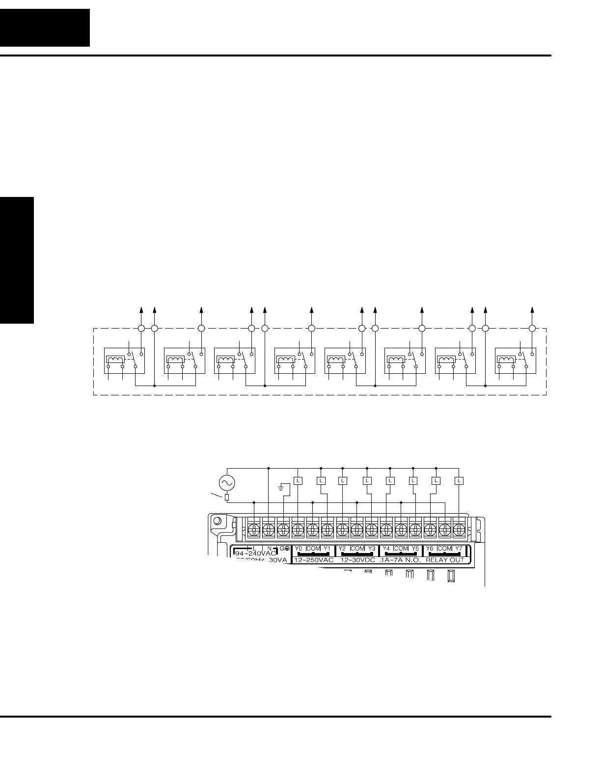
The figure below shows the relays and the internal wiring of the PLC. Note that each
pair is isolated from the other three relay pairs.
Y0
Com
Y1 Y2
Com
Y3 Y4
Com
Y5 Y6
Com
Y7
In the circuit below, all loads use the same AC powersupply which powers the DL105
PLC. In this example, all commons are connected together.
Output Point Wiring
Ground
Neutral
Line
Fuse or
Circuit
Breaker
In the circuit on the following page, loads for Y0 -- Y3 use the same AC power supply
which powers the DL105 PLC. Loads for Y4 -- Y7 use a separate DC supply. In this
example, the commons are separated according to which supply powers the
associated load.
Relay Output
Wiring Methods
 Loading...

