Installation, Wiring,
and Specifications
2--36
Installation, Wiring, and Specifications
DL105 PLC User Manual, 3rd Edition
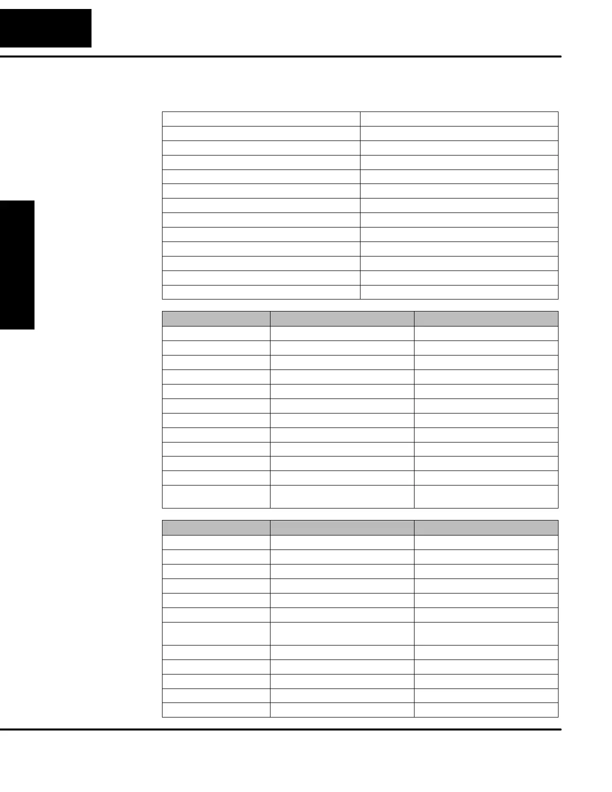
other field devices. In fact, it can be used as the DC supply for switches or sensors in
the input circuit, or for loads in the DC output circuits (up to 0.5 A).
External Power Requirements 100 -- 240 +10% --15%
Communication Port K--Sequence, 9600 baud, 8 data bits, odd parity
Programming cable type D2--DSCBL
Internal Field Supply Ratings +24VDC , 0.5A maximum, isolated
Operating Temperature
32 to 140 F(0to60_ C)
Storage Temperature
--4to158 F (-- 20 to 70_ C)
Relative Humidity 5 to 95% (non-condensing)
Environmental air No corrosive gases permitted
Vibration MIL STD 810C 514.2
Shock MIL STD 810C 516.2
Noise Immunity NEMA ICS3--304
Terminal Ty pe Removable
Wire Gauge One AWG14 or two AWG16, AWG24 minimum
Parameter High--Speed Inputs, X0 -- X3 Standard DC Inputs X4 -- X11
Input Voltage Range 10 -- 26.4 VDC 10 -- 26.4 VDC or 21.6 -- 26.4 VAC
Maximum Voltage 30 VDC (5 kHz maximum frequency) 30 VDC
Minimum Pulse Width
100 μs
N/A
ON Voltage Level >9.0VDC >9.0VDC
OFF Voltage Level <2.0VDC <2.0VDC
Input Impedance
2.8 kΩ @12--24VDC 2.8 kΩ @12--24VDC
Minimum ON Current >3 mA >3 mA
Maximum OFF Current <0.5mA <0.5 mA
OFF to ON Response
<50 μS
2 -- 8 mS, 4 mS typical
ON to OFF Response
<50μS
2 -- 8 mS, 4 mS typical
Status Indicators Logic side Logic side
Commons 4 channels / common x 1 bank 4 channels / common x 1 bank,
2 channels / common x 1 bank
Parameter Pulse O utputs, Y0 -- Y1 Standard Outputs, Y2 -- Y7
Operating Voltage 5--30VDC 5--30VDC
Peak Voltage 60 VDC (7 kHz maximum frequency) 60 VDC
On Voltage Drop 0.4 VDC @ 0.25A 0.4 VDC @ 0.5A
Max Current (resistive) 0.5 A / point (subject to derating) 1.0 A / point (subject to derating)
Max leakage current
15 μA@30VDC 15 μA@30VDC
Max inrush current 1.5 A for 10 mS, 0.5 A for 100 mS 3Afor10mS,1Afor100mS
External DC power required 10 -- 30 VDC @30 mA,
plus load current
10 -- 30 VDC @30 mA,
plus load current
OFF to ON Response
<10 μs 3.5 μs
ON to OFF Response
<70 μs 110 μs
Status Indicators Logic Side Logic Side
Commons Internally connected Internally connected
Fuses None None
F1--130DD/
F130--DD--CE
General
Specifications
DC Input
Specifications
DC Output
Specifications
 Loading...

