Q-3
(A)
Photoelectric
Sensors
(B)
Fiber
Optic
Sensors
(C)
Door/Area
Sensors
(D)
Proximity
Sensors
(E)
Pressure
Sensors
(F)
Rotary
Encoders
(G)
Connectors/
Connector Cables/
Sensor Distribution
Boxes/Sockets
(H)
Temperature
Controllers
(I)
SSRs/Power
Controllers
(J)
Counters
(K)
Timers
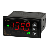
(L)
Panel
Meters
(M)
Tacho/
Speed/Pulse
Meters
(N)
Display
Units
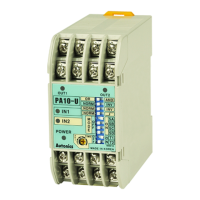
(O)
Sensor
Controllers
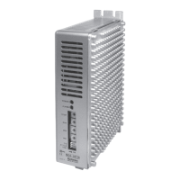
(P)
Switching
Mode Power
Supplies
(Q)
Stepper Motors
& Drivers
& Controllers
(R)
Graphic/
Logic
Panels
(S)
Field
Network
Devices
(T)
Software
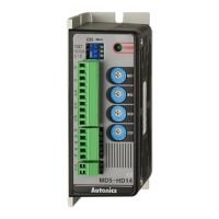
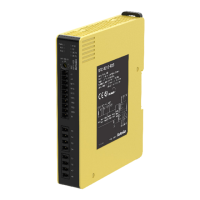
Small, Light, High Speed & Torque 5-Phase Stepper Motor Driver
● Bipolar constant pentagon drive method
● Includes auto current down and self-diagnosis function
● Low speed rotation and high accuracy controlling with
microstep-driving (MD5-HD14, MD5-HF14, MD5-HF14-AO,
MD5-HF28)
[Max. resolution - 250 division / In case of 5-phase stepper
motor of which basic step angle is 0.72°, it enables to
control up to 0.00288° per pulse and it requires 125,000
pulses per rotation.]
● Photocoupler input insulation method to minimize the
effects from external noise
Ordering Information
Specifications
Features
Item
Motor phase
Step type (resolution)
Power supply
RUN current
Output
MD 145 H F
No mark Zero point excitation output
※
1
AO Alarm output
14 1.4A/Phase
28 2.8A/Phase
D 20-35VDC
F 100-220VAC
H Micro step (250-division)
N Normal Step
5 5-Phase
MD Motor Driver
※
1: Except MD5-ND14
※
KR-55MC can be replaced with MD5-HD14.
※
KR-5MC can be replaced with MD5-ND14.
※
MD5-MF14 can be replaced with MD5-HF14.
※
KR-505G can be replaced with MD5-HF28.
Please read “Safety Considerations” in operation
manual before using.
MD5-HD14
MD5-ND14
MD5-HF14-AO
MD5-HF14
MD5-HF28
ᜡ
ᜡ
90 to 110% of the rated voltage
Max. current consumption
※
2
27 to 90% of RUN current (set by STOP current switch)
current (set by STOP
Bipolar constant current pentagon drive
1, 2, 4, 5, 8, 10, 16, 20, 25, 40, 50, 80, 100, 125, 200, 250-division (0.72 to 0.00288 /Step)
1, 2-division (0.72 , 0.36 /step)
Input pulse
characteristic
Pulse width
㎲ (CW, CCW), Min. 1ms (HOLD OFF)
Min. 10㎲ (CW, CCW),
Min. 1ms (HOLD OFF)
Duty rate
Rising/Falling time
Pulse input voltage
[H]: 4-8VDCᜡ, [L]: 0-0.5VDC
Pulse input current
7.5-14mA (CW, CCW), 10-16mA (HOLD OFF, DIVISION SELECTION, ZERO OUT)
※
4
Max. input pulse
frequency
※
5
Max. 50kHz (CW, CCW)
270Ω (CW, CCW),
390Ω (HOLD OFF, DIVISION SELECTION),
10Ω (ZERO OUT)
270Ω (CW, CCW),
390Ω (HOLD OFF),
10Ω (ALARM)
390Ω (HOLD OFF,
DIVISION SELECTION),
390Ω
(CW, CCW, HOLD OFF)
Over 100MΩ (at 500VDC megger, between all terminals and case)
1000VAC 50/60Hz for 1min (between all terminals and case)
±500V the square wave
noise (pulse width: 1
μs
±2kV the square wave noise (pulse width: 1μs) by the noise simulator
noise (pulse width: 1μs
1.5mm amplitude at frequency 5 to 60Hz (for 1 min) in each X, Y, Z direction for 2 hours
1.5mm amplitude at frequency 5 to 60Hz (for 1 min) in each X, Y, Z direction for 10 min
Ambient temp.
0 to 40℃,
storage: -10 to 60℃
℃, storage: -10 to 60℃
0 to 40℃,
storage: -10 to 60℃
35 to 85%RH, storage: 35 to 85%RH
ᜢ ᜢ
※
6
Approx. 327.5g
(approx. 220g)
Approx. 840g
(approx. 680g)
Approx. 820g
(approx. 660g)
Approx. 1.35kg
(approx. 1.2kg)
Approx. 183g
(approx. 130g)
※
1: When using over 30VDC power supply, torque characteristics are improved but the driver temperature raise. The unit should be installed at the well ventilation
environment.
※
2: Based on ambient temperature 25
℃
, ambient humidity 55%RH.
※
3: RUN current varies depending on the input RUN frequency and max. RUN current at the moment varies also varies depending on the load.
※
4: In case of MD5-HF14-AO, MD5-ND14, there are no DIVISION SELECTION, ZERO OUT function.
※
5: Max. input pulse frequency is max. frequency to be input and is not same as max. pull-out frequency or max. slewing frequency.
※
6: The weight includes packaging. The weight in parenthesis is for unit only.
※
Environment resistance is rated at no freezing or condensation.
MD5 Series
5-Phase Stepper Motor Driver
(only for MD5-HF14,
MD5-HF28 model)