Q-17
(A)
Photoelectric
Sensors
(B)
Fiber
Optic
Sensors
(C)
Door/Area
Sensors
(D)
Proximity
Sensors
(E)
Pressure
Sensors
(F)
Rotary
Encoders
(G)
Connectors/
Connector Cables/
Sensor Distribution
Boxes/Sockets
(H)
Temperature
Controllers
(I)
SSRs/Power
Controllers
(J)
Counters
(K)
Timers
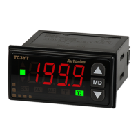
(L)
Panel
Meters
(M)
Tacho/
Speed/Pulse
Meters
(N)
Display
Units
(O)
Sensor
Controllers
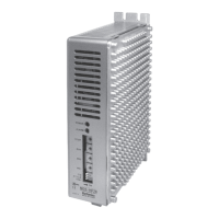
(P)
Switching
Mode Power
Supplies
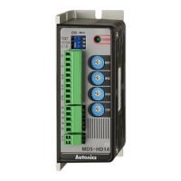
(Q)
Stepper Motors
& Drivers
& Controllers
(R)
Graphic/
Logic
Panels
(S)
Field
Network
Devices
(T)
Software
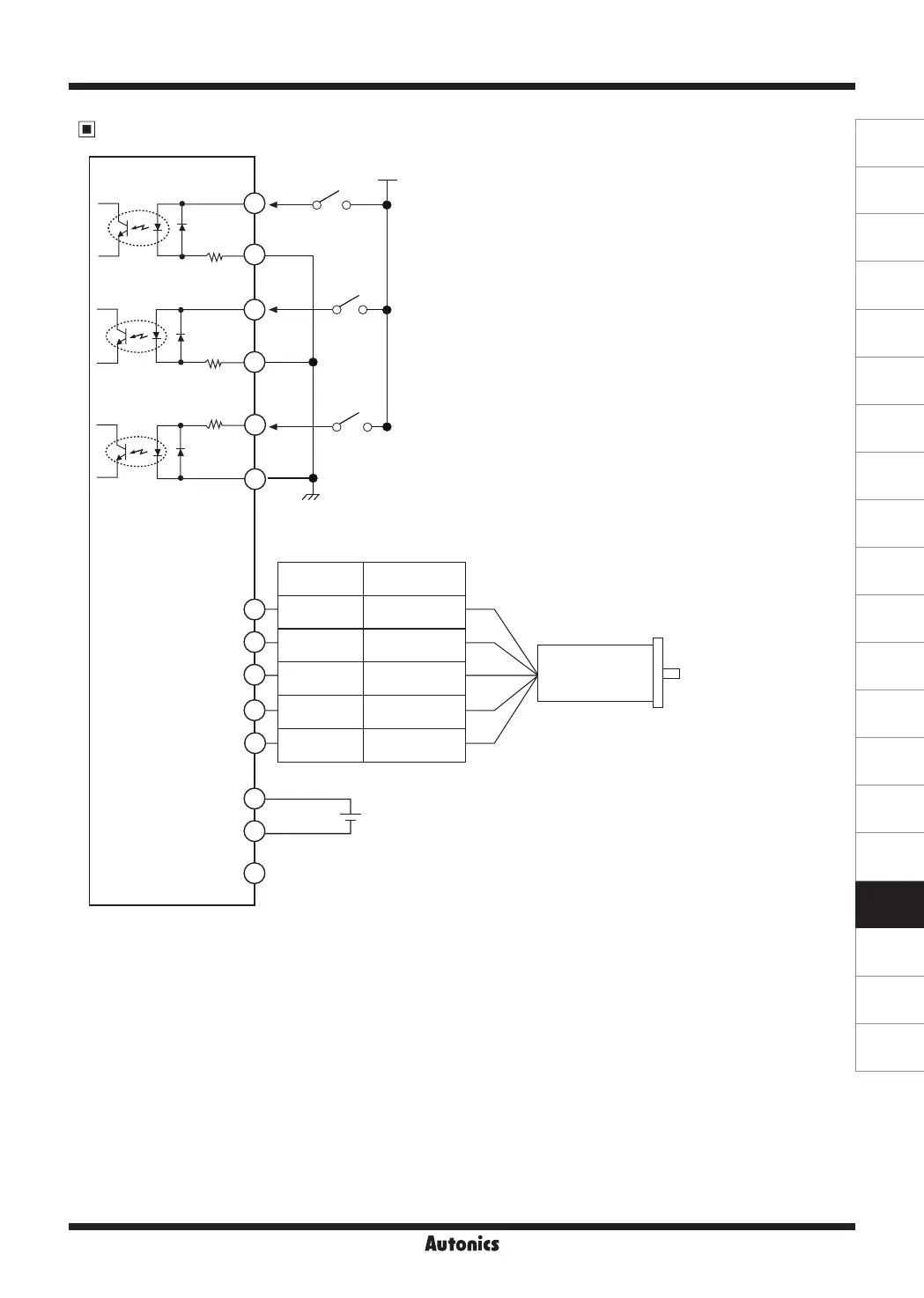
I/O Circuit and Connections
※
CW
2-pulse input method (CW rotation signal input)
1-pulse input method (operating rotation signal input)
※
CCW
2-pulse input method (CCW rotation signal input)
1-pulse input method (rotation direction signal input)
→ [H]: CW, [L]: CCW
※
HOLD OFF
Control signal for motor excitation OFF
→ [H]: Motor excitation OFF
※
If the power for driving pulse from external is over
than +5VDC, please connect resistor at the outside.
(input voltage max. 24VDC, input current 10-20mA)
※
This connection cable color is only for Autonics motors.
It may different cable color when using other motors.
※
In case of standard connection, refer to Q-40 page.
+5VDC
390Ω
390Ω
390Ω
CCW
CW
+5VDC Max. 30mA output
Power
20-35VDC
6
5
4
3
1
2
+
-
GND
HOLD
OFF
[Motor]
[Power]
[Signal]
1
2
3
BLUE
RED
ORANGE
GREEN
BLACK
Motor
Pentagon
connection
Standard
connection
Blue Gray+Red
Red Yellow+Black
Orange Orange+White
Green Brown+Green
Black Blue+Purple
5
4
3
1
2
5-Phase Stepper Motor Driver (1.5A/Phase, DC Power)
 Loading...