Q-23
(A)
Photoelectric
Sensors
(B)
Fiber
Optic
Sensors
(C)
Door/Area
Sensors
(D)
Proximity
Sensors
(E)
Pressure
Sensors
(F)
Rotary
Encoders
(G)
Connectors/
Connector Cables/
Sensor Distribution
Boxes/Sockets
(H)
Temperature
Controllers
(I)
SSRs/Power
Controllers
(J)
Counters
(K)
Timers
(L)
Panel
Meters
(M)
Tacho/
Speed/Pulse
Meters
(N)
Display
Units
(O)
Sensor
Controllers
(P)
Switching
Mode Power
Supplies
(Q)
Stepper Motors
& Drivers
& Controllers
(R)
Graphic/
Logic
Panels
(S)
Field
Network
Devices
(T)
Software
5. For installation
①
The unit must be installed with heat protection.
The conditions of
②
,
③
should be satisfied.
(
※
MD5-ND14)
②
In order to increase heat protection efficiency of the
driver, must install the heat sink close to metal panel and
keep it well-ventilated.
③
Excessive heat generation may occur on driver. Keep the
heat sink under 80
℃
when installing the unit.
(at over 80
℃
, forcible cooling shall be required.)
④
If the unit is installed in distribution panel, enclosed
space or place with heat, it may cause product damage
by heat. Install a ventilation. (only for MD5-HF28)
⑤
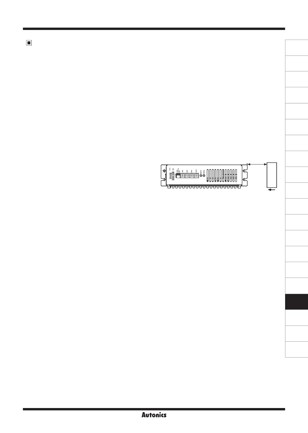
For heat radiation of driver, install a fan as below figure.
(distance between the
ⓐ
fan and the unit: approx. within
70mm,
ⓑ
min. airflow: 0.71m
3
/min at least)
(only for MD5-HF28)
6. For using setting switches
①
Be sure that the TEST switch is OFF before supplying
the power. If the TEST switch is ON, the motor operates
immediately and it may be dangerous.
(except MD5-ND14)
②
Do not change any setting switch during the operation or
after supplying power. It may cause malfunction.
7. Autonics motor driver does not prepare
protection function for a motor.
8. This product may be used in the following
environments.
①
Indoors
②
Altitude max. 2,000m
③
Pollution degree 2
④
Installation category
Ⅱ
Cautions during Use
(common Specifications of 5-Phase Stepper Motor Driver)
1. For signal input
①
Do not input CW, CCW signal at the same time in 2-pulse
input method. Failure to follow this instruction may result
in malfunction. It may not operate properly if another
direction signal is inputted when one of CW or CCW is [H].
②
When the signal input voltage is exceeded the rated
voltage, connect additional resistance at the outside.
2. For RUN current, STOP current setting
①
Set RUN current within the range of motor's rated
current. Failure to follow this instruction may result in
severe heat of motor or motor damage.
②
If motor stops, switching for STOP current executed by
the current down function. When hold off signal is [H]
or current down function is OFF, the switching does not
execute. (except MD5-ND14)
③
Use the power for supplying sufficient current to the motor.
④
Check the polarity of power before operating the unit.
(only for MD5-HD14, HD14-2X/3X, ND14)
3. For rotating motor
(only for MD5-HD14, HD14-2X/3X, ND14)
①
For rotating the motor when driver power turns OFF,
separate the motor from the driver.
(if not, the driver power turns ON)
②
For rotating the motor when driver power turns ON, use
Hold OFF function.
4. For cable connection
①
Use twisted pair (over 0.2mm
2
) for the signal cable which
should be shorter than 2m.
②
The thickness of cable should be same or thicker than
the motor cable's when extending the motor cable.
③
Must separate between the signal cable and the power
cable over 10cm.
5-Phase Stepper Motor Driver
ⓐ
ⓑ
Air Flow
 Loading...