EasyManuals Logo

Autonics MD5 Series User Manual

Autonics MD5 Series
21 pages
To Next Page IconTo Next Page
To Previous Page IconTo Previous Page
Page #7 background imageLoading...
Page #7 background image
Q-9
(A)
Photoelectric
Sensors
(B)
Fiber
Optic
Sensors
(C)
Door/Area
Sensors
(D)
Proximity
Sensors
(E)
Pressure
Sensors
(F)
Rotary
Encoders
(G)
Connectors/
Connector Cables/
Sensor Distribution
Boxes/Sockets
(H)
Temperature
Controllers
(I)
SSRs/Power
Controllers
(J)
Counters
(K)
Timers
(L)
Panel
Meters
(M)
Tacho/
Speed/Pulse
Meters
(N)
Display
Units
(O)
Sensor
Controllers
(P)
Switching
Mode Power
Supplies
(Q)
Stepper Motors
& Drivers
& Controllers
(R)
Graphic/
Logic
Panels
(S)
Field
Network
Devices
(T)
Software
Connections
Dimensions
(unit: mm)
Please refer to Q-40 for
standard wiring.
Division selection
signal
F.G.
Zero point excitation
output signal
+
-
+
-
Black
Green
Orange
Red
Blue
Motor
100-220VAC 50/60Hz
CW+
CW-
CCW+
CCW-
HOLD OFF+
HOLD OFF-
User
Controller
5
42
40
156
20
108
122
133.5
5.4
4-M4 Tap Depth: 8
7
120
170
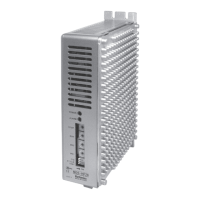
5-Phase Stepper Motor Driver (1.4A/Phase, AC Power)

Other manuals for Autonics MD5 Series

Questions and Answers:

Question and Answer IconNeed help?

Do you have a question about the Autonics MD5 Series and is the answer not in the manual?

Autonics MD5 Series Specifications

General IconGeneral
BrandAutonics
ModelMD5 Series
CategoryController
LanguageEnglish

Related product manuals