Q-20
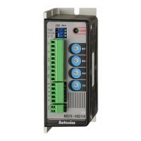
MD5 Series
Functions
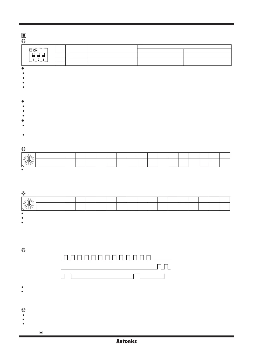
Function selection DIP switch
No. Name Function
Switch position
ON OFF (default)
1 TEST Self diagnosis function 30rpm rotation Not use
2 1/2 CLK Pulse input method 1-pulse input method 2-pulse input method
3 C/D Auto Current Down Not use Use
TEST
Self diagnosis function is for motor and driver test.
This function makes the motor rotate with 30rpm in full step. Rotation speed varies with resolution settings.
Rotation speed = 30rpm/resolution
In 1-pulse input method, it rotates to CCW, and in 2-pulse input method, it rotates to CW.
※
Be sure that the TEST switch is OFF before supplying the power.
If the TEST switch is ON, the motor operates immediately and it may be dangerous.
1/2 CLK
1/2 CLK switch is to select pulse input method.
1-pulse input method: CW → operating rotation signal input, CCW → rotation direction signal input ([H]: CW, [L]: CCW)
2-pulse input method: CW → CW rotation signal input, CCW → CCW rotation signal input.
C/D (auto current down)
This function is to reduce the current provided for motor automatically for preventing severe motor's heat when motor
stops.
If motor RUN pulse is not applied, the current provided for motor reduces as the set STOP current.
※
Be sure that when motor RUN current is reduced, the stop torque of motor also reduced.
※
Set the STOP current by the Setting STOP current switch.
Setting RUN current
Setting RUN current is for the current provided for motor when the motor runs.
※
When RUN current is increased, RUN torque of the motor is also increased.
※
When RUN current is set too high, the heat is severe.
※
Set RUN current within the range of motor's rated current according to its load.
※
Change RUN current only when the motor stops.
Setting STOP current is for the current provided for motor when the motor stops.
This setting is applied when using C/D (current down) function.
Setting value of STOP current is percentage (%) ratio of the set RUN current.
E.g.) Set RUN current as 1.4A and STOP current as 40%.
STOP current is set as 1.4A×0.4=0.56A
※
When STOP current is decreased, STOP torque of the motor is also decreased.
※
When STOP current is set too low, the heat is lower.
※
Change STOP current only when the motor stops.
Setting STOP current
Zero point excitation output signal (ZERO OUT) [Option]
CW Pulse
CCW Pulse
ZERO OUT
ON
OFF
ON
OFF
ON
OFF
0 0 01 1 12 23 4 5 6 7 8 9
This output indicates the initial step of excitation order of stepper motor and rotation position of motor axis.
This signal outputs every 7.2° of rotation of the motor axis regardless of resolution.
(50 outputs per 1 rotation of the motor.)
E.g.) Full step: outputs one time by 10 pulses input,
20-division: outputs one time by 200 pulses input.
Switch No. 0 1 2 3 4 5 6 7 8 9 A B C D E F
Current (A/Phase) 0.4 0.5 0.57 0.63 0.71 0.77 0.84 0.9 0.96 1.02 1.09 1.15 1.22 1.27 1.33 1.4
Switch No. 0 1 2 3 4 5 6 7 8 9 A B C D E F
% 27 31 36 40 45 50 54 58 62 66 70 74 78 82 86 90
This signal is for rotating motor's axis using external force or used for manual positioning.
When hold off signal maintains over 1ms as [H], motor excitation is released.
When hold off signal maintains over 1ms as [L], motor excitation is in a normal status.
※
Must stop the motor for using this function.
※
Refer to I/O Circuit and Connections.
HOLD OFF function
 Loading...