Q-11
(A)
Photoelectric
Sensors
(B)
Fiber
Optic
Sensors
(C)
Door/Area
Sensors
(D)
Proximity
Sensors
(E)
Pressure
Sensors
(F)
Rotary
Encoders
(G)
Connectors/
Connector Cables/
Sensor Distribution
Boxes/Sockets
(H)
Temperature
Controllers
(I)
SSRs/Power
Controllers
(J)
Counters
(K)
Timers
(L)
Panel
Meters
(M)
Tacho/
Speed/Pulse
Meters
(N)
Display
Units
(O)
Sensor
Controllers
(P)
Switching
Mode Power
Supplies
(Q)
Stepper Motors
& Drivers
& Controllers
(R)
Graphic/
Logic
Panels
(S)
Field
Network
Devices
(T)
Software
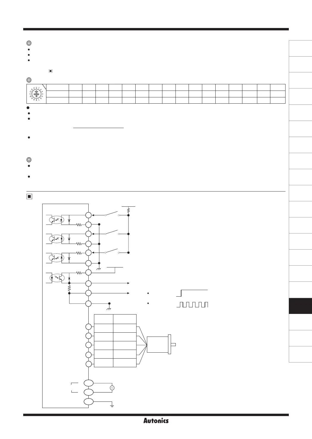
I/O Circuit and Connections
This signal is for rotating motor's axis using external force or used for manual positioning.
When hold off signal maintains over 1ms as [H], motor excitation is released.
When hold off signal maintains over 1ms as [L], motor excitation is in a normal status.
※
Must stop the motor for using this function.
※
Refer to I/O Circuit and Connections.
HOLD OFF function
Alarm output function
Overheat: When the temperature of driver base is over 80
℃
, alarm indicator (red) turns ON and motor stops with holding
the excision. Turn OFF the power and remove the causes. Turn ON the power and alarm output is OFF.
Overcurrent: When overcurrent is applied from motor damage by burn, driver damage, or error, alarm LED (red) is
flashed. When overcurrent occurs, the motor becomes HOLD OFF. Turn OFF the power and remove the causes to
normal operation.
Switch No. 0 1 2 3 4 5 6 7 8 9 A B C D E F
Resolution 1 2 4 5 8 10 16 20 25 40 50 80 100 125 200 250
Step angle 0.72° 0.36° 0.18° 0.144° 0.09° 0.072° 0.045° 0.036°
0.0288°
0.018°
0.0144°
0.009°
0.0072° 0.00576° 0.0036° 0.00288°
Setting Microstep (microstep: resolution)
Setting Resolution (MS1)
The set step angle is dividing basic step angle (0.72°) of 5-phase stepper motor by setting value.
The calculation formula of divided step angle is as below.
When using geared type motor, the angle is step angle divided by gear ratio.
Step angle / gear ratio = Step angle applied gear
E.g) 0.72° / 10 (1:10) = 0.072°
※
Must stop the motor before changing the resolution.
Set step angle =
Basic step angle (0.72°)
Resolution
BLUE
RED
ORANGE
GREEN
BLACK
L
N
100-220VAC
50/60Hz
GND
Motor
G
AC
AC
5
4
3
2
1
1
2
3
4
5
6
7
9
10
270Ω
270Ω
390Ω
10Ω
2kΩ
CW
CCW
HOLD OFF
5-24VDC
+5VDC
Alarm OUT -
Alarm OUT +
8
Power
Pentagon
connection
Standard
connection
Blue Gray+Red
Red Yellow+Black
Orange
Orange+White
Green Brown+Green
Black Blue+Purple
[Motor]
[Power]
[Signal]
※
This connection cable color is only for Autonics motors.
It may different cable color when using other motors.
※
CW
2-pulse input method (CW rotation signal input)
1-pulse input method (operating rotation signal input)
※
CCW
2-pulse input method (CCW rotation signal input)
1-pulse input method (rotation direction signal input)
→ [H]: CW, [L]: CCW
※
HOLD OFF
Control signal for motor excitation OFF
→ [H]: Motor excitation OFF
※
When alarm occurs, the motor becomes HOLD OFF. Turn OFF
the power and remove the causes to normal operation.
Over heat:
Over current:
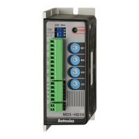
5-Phase Stepper Motor Driver (1.4A/Phase, AC Power, Alarm Output)
※
1: If the power for driving pulse from external is over than +5VDC,
please connect resistor at the outside.
(input power max. 24VDC, input current 10-24mA)
※
1
 Loading...