14
500 SeriesDescription of the loader
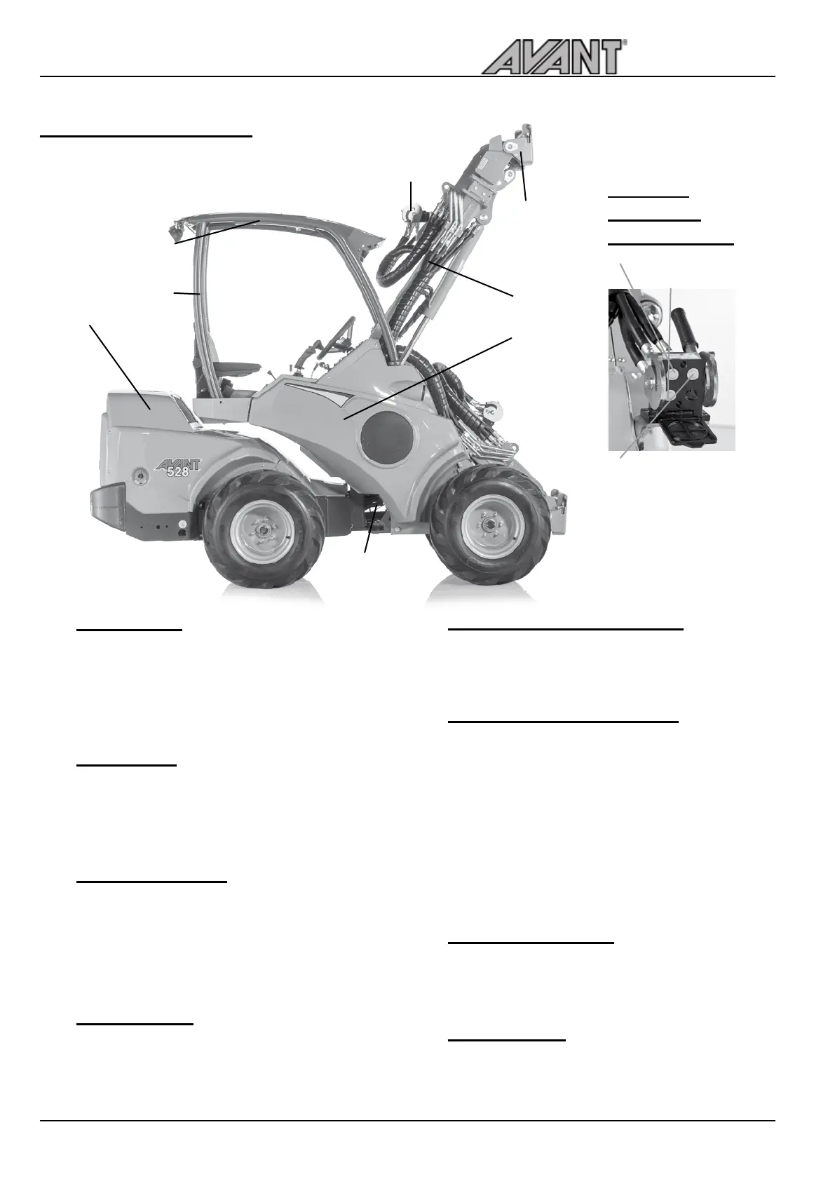
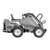
Main parts of the loader
Following picture shows the main parts of the loader:
j
k
l
m
n
o
p
q
j
k
l
m
Front frame
On the front frame are mounted: driver’s seat,
operating controls, hydraulic control valves, hydraulic
oil tank, auxiliary hydraulics outlet, front wheels,
hydraulic motors and the loader boom with attachment
coupling plate.
Back frame
On the back frame are mounted: engine with
accessories, battery, parking brake, fuel tank,
hydraulic pumps, rear wheels, hydraulic motors,
counterweights.
Articulation joint
Articulation joint connects the front and back frame.
The loader is steered hydraulically by the steering
cylinder which is mounted between the front and
back frames. Hydraulic hoses and electric wires are
conducted through the articulation joint.
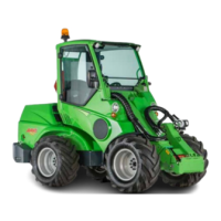
Loader boom
Loader boom is mounted on the front frame with one
pivot pin. The attachment coupling plate is mounted
on the lower end of the boom. The boom is telescopic,
extending 600 mm hydraulically.
n
o
p
q
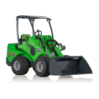
Attachment coupling plate
Attachments are mounted on the attachment coupling
plate. The locking pins on the plate can be operated
manually (standard) or hydraulically (option).
Auxiliary hydraulics outlet
The hydraulic hoses of hydraulically operated
attachments are mounted on this outlet. The outlet
is equipped with the multi connector quick coupling
system and is double acting: it has two pressure
lines and one tank line. In addition, as an option, it
is also possible to install a single or double acting
auxiliary hydraulics outlet in the rear of the machine,
or a double acting outlet in the front under the multi
connector.
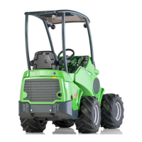
ROPS safety frame
ROPS frame (Roll-over protective structure) complies
with the standard ISO 3471:1994 with Amendment
1:1997 and Technical Corrigendum 1:2000.
FOPS canopy
FOPS canopy (Falling objects protective structure)
mounts on the ROPS. It meets the ISO 3449:2005
FOPS level 1 (1365 J) criteria.
Hydraulic
connectors
Multi connector
Tank line
Pressure 2
Pressure 1