15
2PRODUCT DESCRIPTION
2.1 OVERVIEW
ALS
104
GB
2.1.3 Connection arrangement
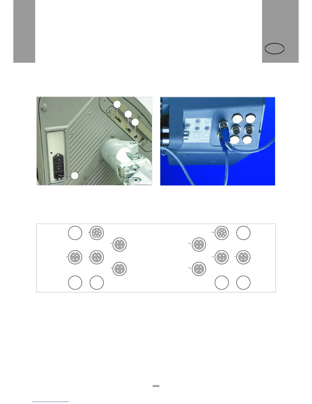
Connections on the back of the device
[6] Connections on the back of the ALS 104:
A Power supply connection
B Signal interface (Sub-D15 port)
C RS232 interface (Sub-D9 port)
D Connection for external control panel (PS/2 port)
Sensor connections
[7] Position of the sensor connections on the ALS 104
[8] Arrangement of the sensor connections (schematic) on the LH (left figure) and RH (right figure) devices.
A Product sensor
B Label sensor
C Optional: Signal outputs
D Speed sensor (required for automatic speed adaption)
E Roll diameter sensor
A
B
C
D
LH RH
AA
B B
CC
D D EE


 To Next Page