EN 12
C - INSTALLATION
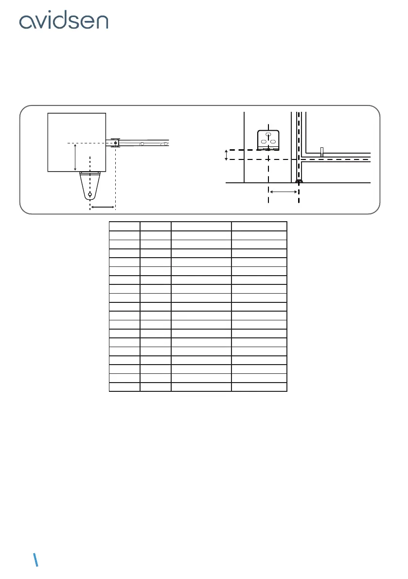
• Measure distance D, then refer to the table for distance B, which allows you to determine the post
mounting bracket position. The table also indicates the hole in which the actuator will be mounted on the
mounting bracket on the gate.
• The height of the centre of the mounting bracket must be the same as the centre of the gate frame on
which the actuator is mounted.
D
B
post
B
23mm
D (mm) B (mm) post bracket hole max angle (°)
0 150 4 120°
10 150 4 120°
20 160 4 120°
30 150 4 115°
40 160 4 or 5 115°
50 150 4 110°
60 155 5 110°
70 145 4 or 5 105°
80 150 5 105°
90 135 5 100°
100 140 5 100°
110 145 5 100°
120 130 5 95°
130 135 5 95°
140 120 5 90°
150 115 5 90°
160 110 5 90°
170 100 5 90°
Mark the location of the holes in the post, ensuring that the post mounting bracket is mounted horizontally
at the end. Use 10-inch lag screws or any other fastening system suitable for the post material.
Please note: there will be signicant force on the mounting bracket when the engine is running. We
recommend sealing threaded rods at least 15 cm in length. If the post is made of metal, we recommend
welding or passing the threaded rods through to secure them with self-locking nuts.
Consult a professional if in doubt.
Turn the actuator over and make sure the carriage rod is about 5mm from the opposite end of the motor.
Otherwise, move the carriage using a 9V LR61 battery. The motors can also be connected to the electronic
card (see connection section) and manual mode can be started in order to power the motors while adjusting
the position of the carriage.