http://www.avl.com
Frequency Outputs
26
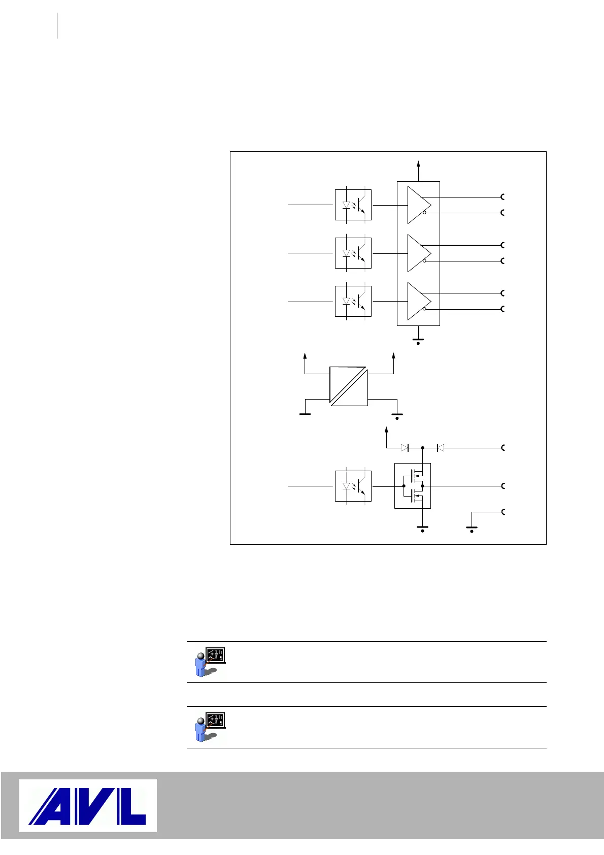
4.2 Frequency Outputs
4.2.1 Block Diagram
The pin assignment above applies to X15 and X16.
The output frequency and the duty cycle can be varied over a wide
range. In practical operation, only one of the two quantities will be
varied - the other quantity will remain unvaried.
Fig. 14 Circuit of F-OUT channel
X15/1
X15/2
Zero track
X15/3
X15/4
Track A
X15/5
X15/6
Track B
5 V
5 V
X15/7
X15/8
X15/9
5...24 V
Zero track
Track A
Track B
Single track
Vcc
5 V
Example: The desired analog value (demand engine speed of 900 –
8000 rpm) is mapped to a duty-cyle range of 5 % to 95 %. The
frequency is set at 1 kHz.
Example: The desired output quantity (demand torque of 20 – 200
Nm) is mapped to a frequency range of 200 Hz to 2000 Hz. The duty
cycle is always 50 %.
 Loading...

