System Environment
F-FEM-DAC
F-FEM-DACF-FEM-DAC
F-FEM-DAC
Operating Manual
5
1.3 System Environment
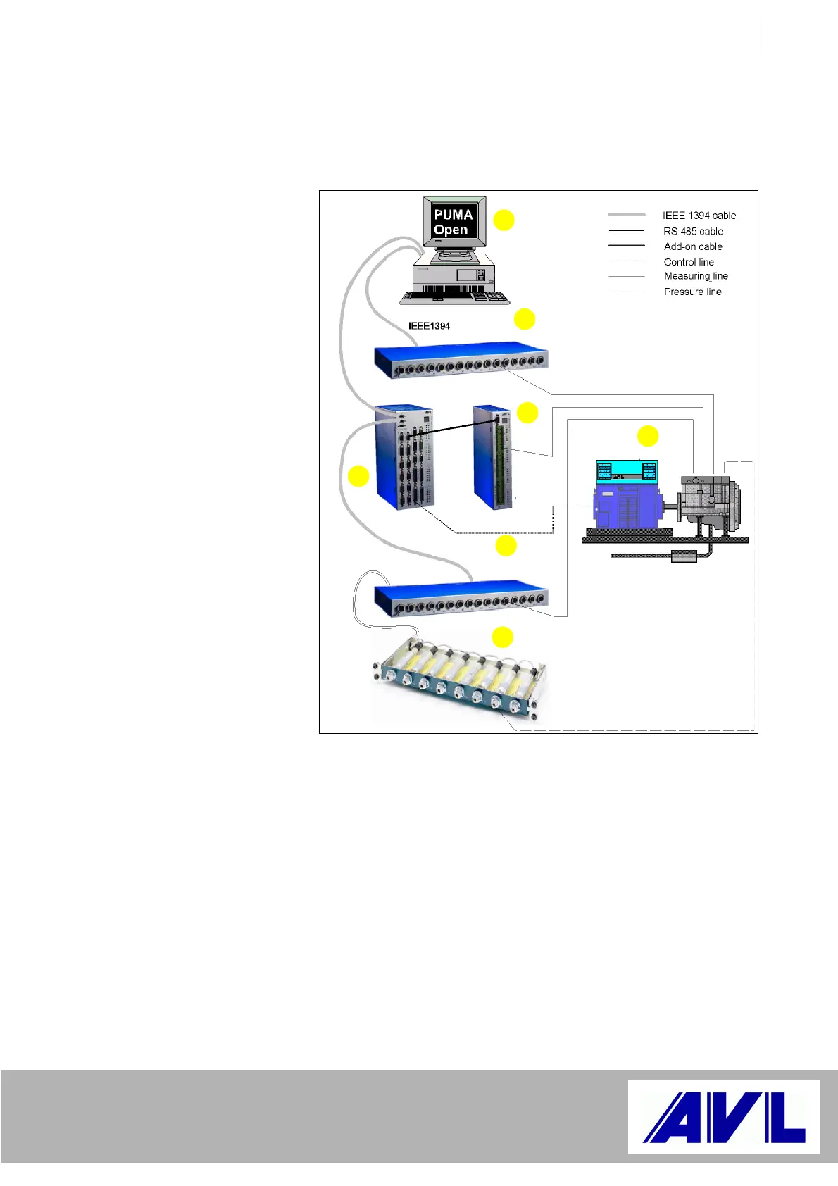
The figure below outlines schematically how F-FEMs are integrated
with the PUMA Open test bed system.
Fig. 2 Example of a system environment
1 Test bed PC (on which the PUMA Open system has been
installed)
2 Engine test bed (engine, dyno)
3 F-FEM-AIF, directly connected to the PUMA Open system
4 F-FEM-CON, directly connected to the PUMA Open system
5 F-FEM-DIO, connected to the PUMA Open system via
F-FEM-CON
6 F-FEM-AIN or F-FEM-AIS (electrically isolated), connected
to the PUMA Open system via F-FEM-CON
7 FEM P, connected to the PUMA Open system via
F-FEM-AIN or F-FEM-AIS
1
3
4
5
2
6
7
 Loading...

