http://www.avl.com
Frequency Outputs
32
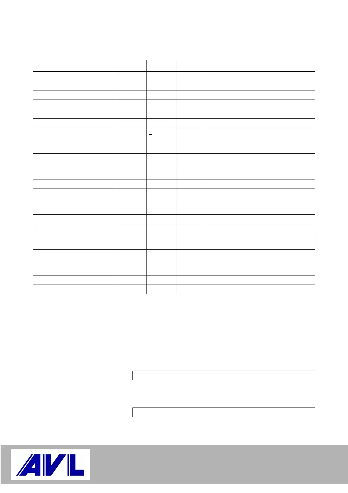
4.2.4 Specifications
Positive and negative frequencies can be generated. Interpretation:
The output of a positive frequency corresponds to a right-hand rotation.
Track A leads with respect to track B. If the frequency turns negative,
this indicates that the direction of rotation is reversed - track A will lag
with respect to track B (left-hand rotation!)
Relationship between duty cycle and phase angle:
or
Quantity Min. Max. Unit Remark
Time resolution 25 ns 1 LSB
Frequency resolution 0.074506 Hz 1 LSB
Number of teeth Z
n
2 65535 Teeth
Duty Cycle DC 0.001 + 99.999 %
Output frequency f
AB
- 300 + 300 kHz In Simulate ABZ mode
Output frequency f
Out
- 300 + 300 kHz In PWM mode
Absolute frequency error +
25 ppm Caused by quartz
Update frequency 1 1000 Hz For new output value, can be parame-
terized
Outputs
at Pins 1 ... 6
Differential outputs according to EIA
standard RS422
Output voltage High 2.5 V With load of 100 W
Output voltage Low 0.5 V With load of 100 W
External voltage applied to the
outputs
30 V Referred to Pin 9
without damage
Output Current 30 mA Short circuit-proof
Rise/fall time 6 ns Load: 40 pF parallel 100 W
Output at Pin 8 Single channel, single track
Output voltage High 4.5 15 V Maximum value
when applying 24 V at Pin 7
Output voltage Low 0.5 V
External voltage applied to the
output
30 V Referred to Pin 9
without damage
Output Current 50 mA Short circuit-proof
Rise/fall time 40 ns Load: 2.2 nF
Table 4 Specifications
Duty Cycle [%] = Phase Angle [°] / 3.6
Duty Cycle [%] = Phase Angle [°] / 3.6
 Loading...

