http://www.avl.com
Pin assignment
36
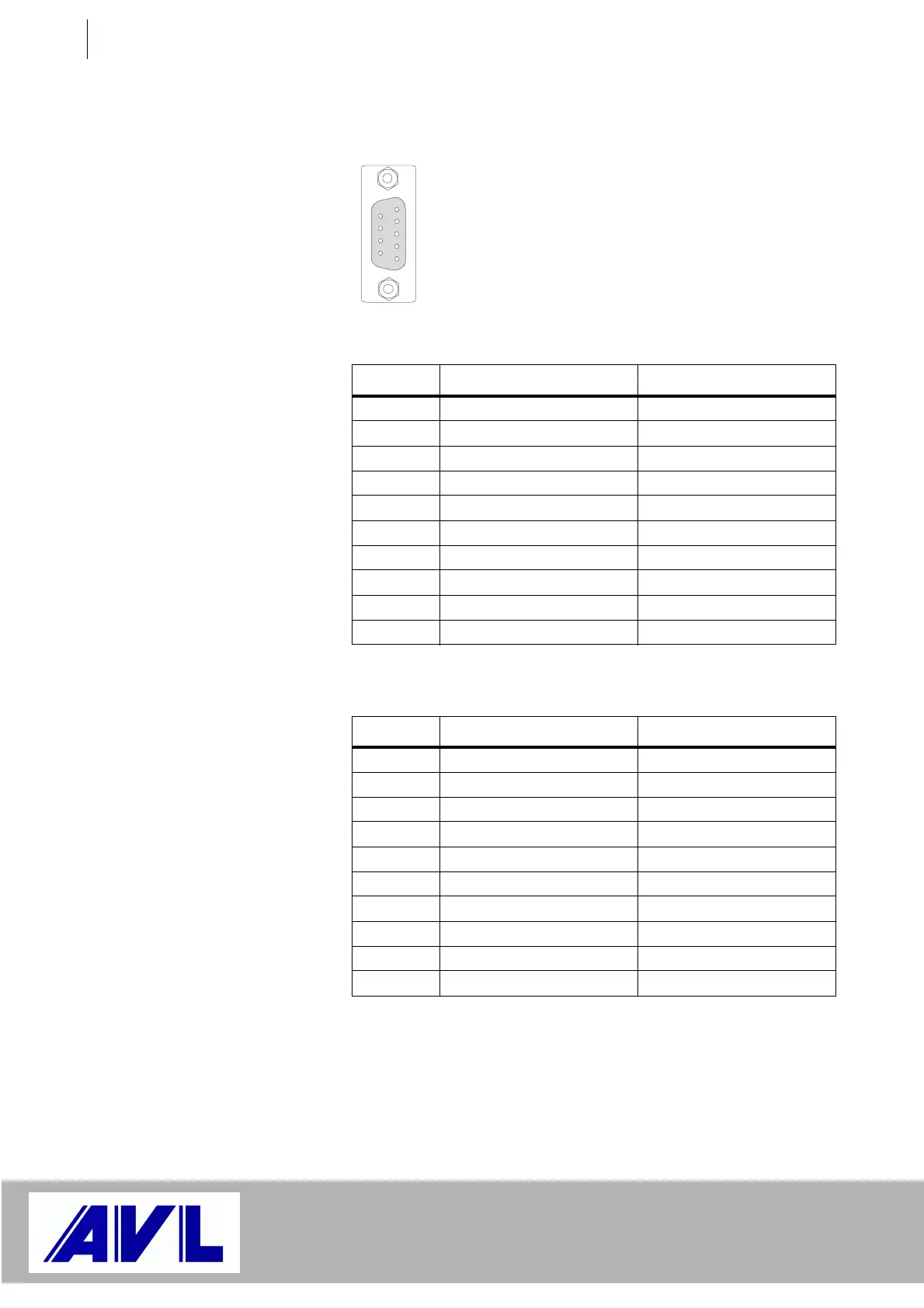
4.5.2 Analog Outputs: X5 ... X8
Uout1- is connected internally to Iout1- and AOGND_1, etc.
If necessary, electrical isolation can be removed and Uout1 be
connected to the digital ground or case ground by bridging pins 5 and 9
resp. 5 and 7 in connector X5, X6, X7 or X8.
Fig. 24 Analog outputs: X5 ... X8
Pin Signal at X5 Signal at X6
1 Uout1– Uout2–
2 Uout1+ Uout2+
3 Iout1+ Iout2+
4 Iout1– Iout2–
5 AOGND_1 (opt.) AOGND_2 (opt.)
6nc nc
7 Shielding (opt.) Shielding (opt.)
8nc nc
9 DGND DGND
Case Shielding Shielding
Table 6
Pin Signal at X7 Signal at X8
1 Uout3– Uout4–
2 Uout3+ Uout4+
3 Iout3+ Iout4+
4 Iout3– Iout4–
5 AOGND_3 (opt.) AOGND_4 (opt.)
6nc nc
7 Shielding (opt.) Shielding (opt.)
8nc nc
9 DGND DGND
Case Shielding Shielding
Table 7
1
 Loading...

