Frequency Outputs
F-FEM-DAC
F-FEM-DACF-FEM-DAC
F-FEM-DAC
Operating Manual
27
4.2.2 Description of Modes
The two frequency outputs can be used in different ways. All possible
signal types are explained below. Only the description for channel 1 is
given; it is identical for channel 2.
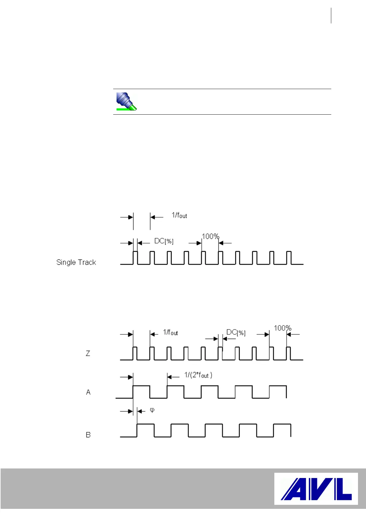
Signal type: PWM, PWM inverted
The desired frequency (single-track signal) is output at the single
channel with the desired duty cycle.
The desired frequency is output by halves at tracks A and B, whereby
the phase shift of both tracks corresponds to the desired duty cycle (0 -
100% corresponds to 0 - 180°).
Important: Some of the functionalities described require the on-board
software revision 3.0.x. For the automation software version to be
used (PUMA Open, EMCON), please refer to the compatibility matrix.
ABsingleout
f2ff
×==
Fig. 15 F-Out PWM single channel
Fig. 16 F-Out PWM tracks Z, A, B
 Loading...

