2018-10-05 | Technical improvements, changes in design, printing- and other errors expected. 7
1.7. Display elements and connectors
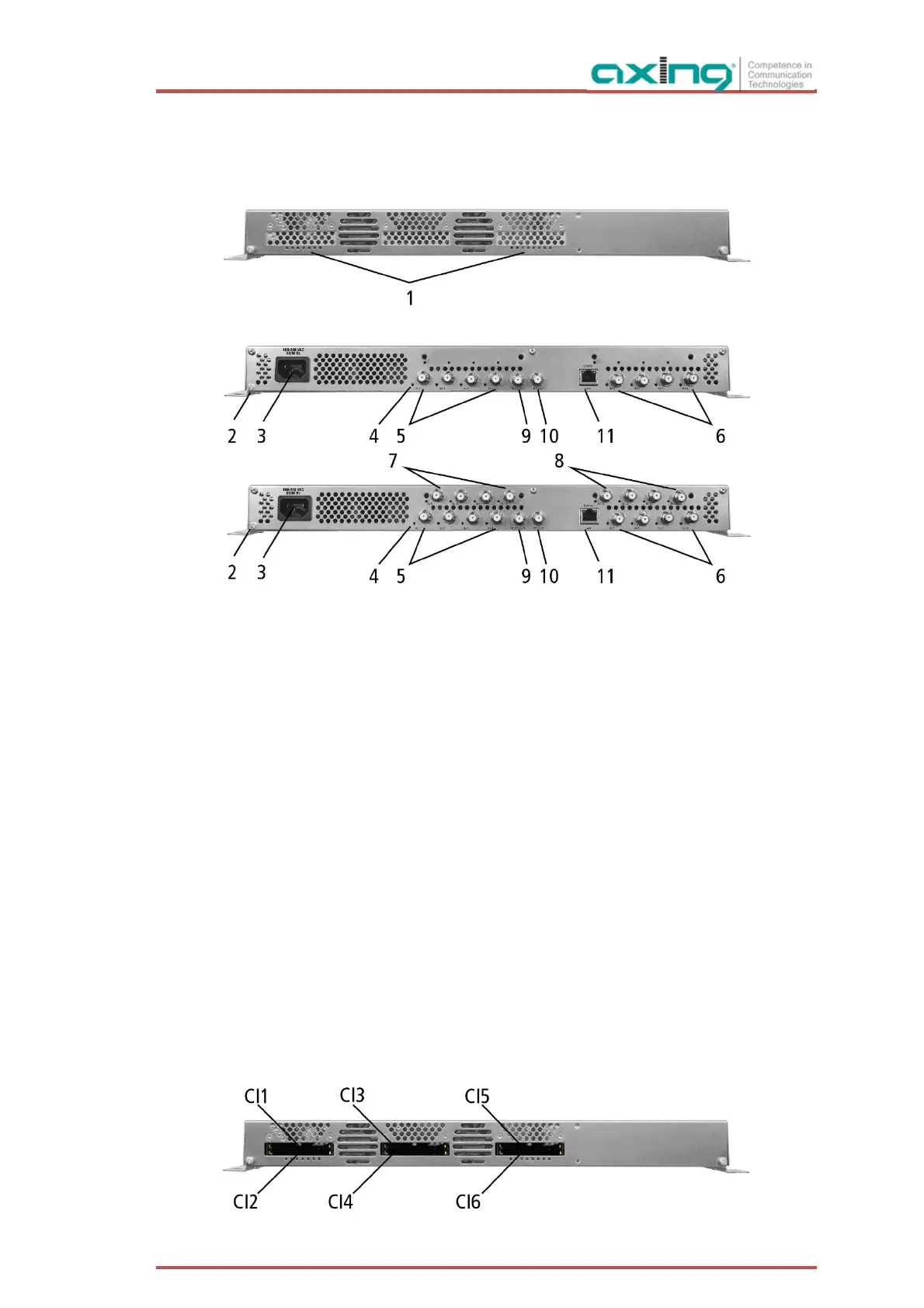
1.7.1. MK 8/16-0x
1. LED indicators
Green = modulation is ok
Green (blinking) = something is missing from the programmed TS
Red = modulator overload.
2. Equipotential bonding connection
3. Mains connection
4. HF input LEDs:
Yellow = MPEG data stream present,
Off = MPEG data stream not present
5. RF input 1…4
6. RF input 5…8
7. RF input 9…12 (MK 16-0x only)
8. RF input 13…16 (MK 16-0x only)
9. Test port
10. RF output
11. RJ45 Ethernet connector
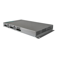
1.7.2. MK 8-06/16-06
MK 8-06 and MK 16-06 each have 6 CI slots (CI1 ... CI6).
Which encrypted program you decrypt with which interface, you determine in the configuration.