USER MANUAL ME-01 11
8. Assembly and connecting external devices
1. To build a scale basing on ME-01 indicator contact authorized manufacturer
service point or use Installation Guide delivered with the indicator (other
brochure).
2. The manufacturer gives a full guaranty for ME-01 indicator only when the
indicator was mounted by AXIS Sp. z o.o. In other cases the guaranty obligation
is taken over by the final contractor of the weighing device.
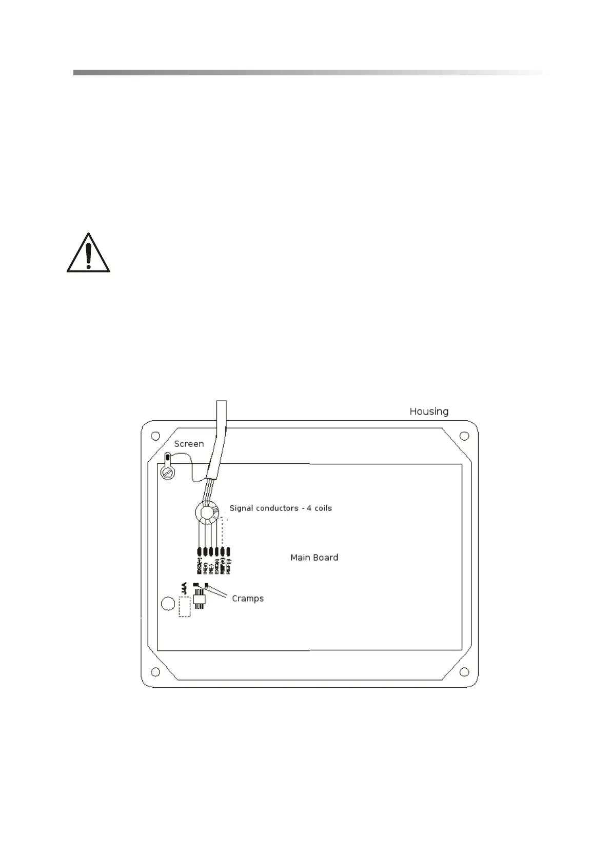
To comply CE marking requirements, for connecting the wires use filtering core
20mm.
The core should be placed within 30mm from the place of its connection.
Single strain gauge scheme inside ME-01:
When 6-wires connection of strain gauge transducers is used (REF+ and REF)
jumpers shown on the picture above should be soldered out from the main board
(load cell wires are connected EXC+, EXC-, IN+,IN- and additionally REF+ and
REF-).
Commonly used wire colors:
EXC+ red
Before connecting the sensors to the indicator unplug the device from the
mains to avoid damaging the indicator.