USER MANUAL ME-01 15
9.1 Transmitter connection
P1-P3 (THRESHOLDS) outputs are used to connect dosing or signalling (option)
devices. There are opto-isolators of an open collector type with 100mA / 24V
maximum load. They can be connected directly to transmitters inputs or to
MS3K/P board offered by AXIS separately or in ST 3K/P control box (3
transmitters, own power supply).
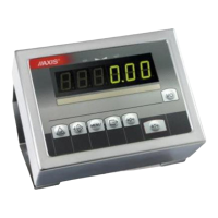
In ME-01/A connection THRESHOLD is placed on indicator’s housing. In
ME-01/N meter connection is placed on conductor.
Optional indicators outer wires have digital markers.
* colors might change
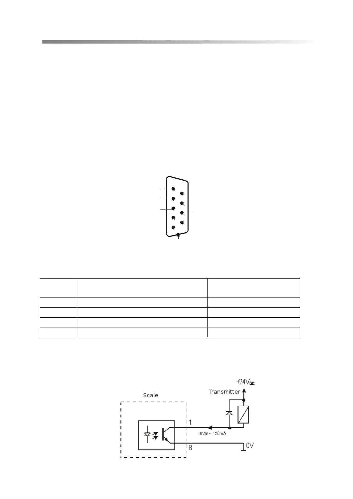
Diagram for direct connect a transmitter to THRESHOLD output:
* in option without an interface – 10 is in the place of 8
ekran
P1 (próg I)
P2 (próg II)
P3 (zero)
masa
1
6
2
7
3
8
4
9
5
P1 (threshold 1)
P2 (threshold 2)
P3 (threshold 3)