9-2
Chapter 9. MAINTENANCE AND TROUBLESHOOTING
Operation in case of PV input failure
(1) AL01, 02, or 03 occurs.
Control output: It is possible to make the settings so that the operation is
continued or discontinued.
Other operation: Operation is continued.
(2) Alarm occurs in cases other than those shown above.
All operations are continued.
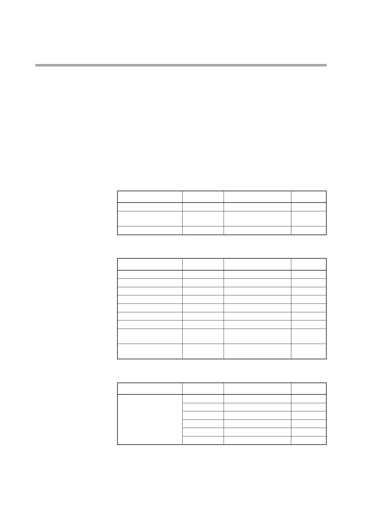
The following table shows the indications and alarms of this unit by the sensor type
if PV input failure occurs:
z
Thermocouple
Failure status Range No. Indication value Alarm code
Sensor burnout Upscale (110%FS)
AL01
CJ failure PV having incorrect cold
contact compensation
AL03
Over-range, burnout 19 (PLII) 1365˚C (105%FS)
AL01
z
RTD
Failure status Range No. Indication value Alarm code
RTD burnout Upscale (110%FS)
AL01
A-wire burnout Upscale (110%FS)
AL01
B-wire burnout Upscale (110%FS)
AL01, AL03
C-wire burnout Upscale (110%FS)
AL01, AL03
2- or 3-wire burnout Upscale (110%FS)
AL01, AL03
A- and B-wire short-circuit Downscale (-10%FS)
AL02
A- and C-wire short-circuit Downscale (-10%FS)
AL02
A- and B-wire/A- and
C-wire short-circuit
41 (Pt100) -235˚C (-5%FS)
AL02
A- and B-wire/A- and
C-wire short-circuit
42 (JPt100) -235˚C (-5%FS)
AL02
z
DC voltage/DC current
Failure status Range No. Indication value Alarm code
Burnout 84 (0 to 1 V) Downscale (-3%FS)
AL02
86 (1 to 5 V) Downscale (-10%FS)
AL02
87 (0 to 5 V) Downscale (-3%FS)
AL02
88 (0 to 10 V) Downscale (0%FS) None
89 (0 to 20 mA) Indefiniteness (near 0%FS) None
90 (4 to 20 mA) Downscale (-10%FS)
AL02