1-4
Chapter 1. OVERVIEW
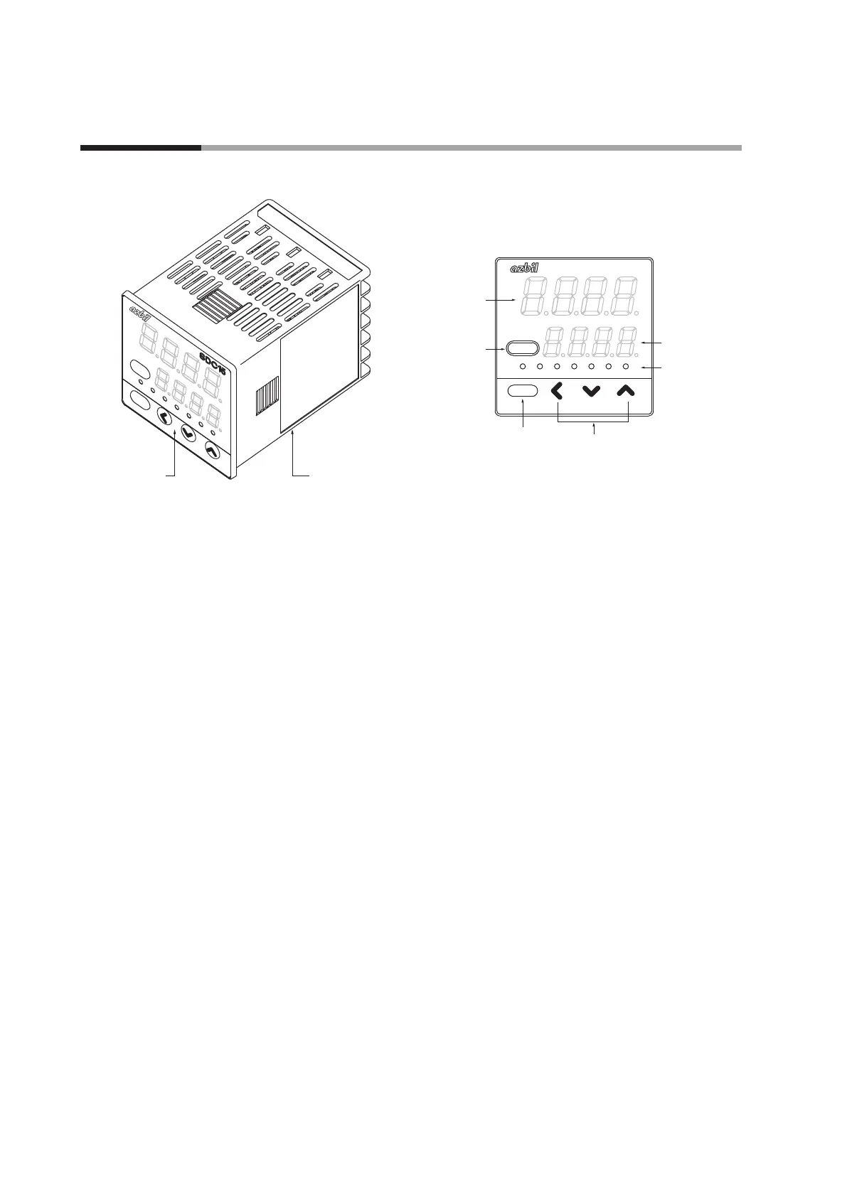
Main unit and console
ot2
ot1
ev3
ev2
ev1
man
rdy
para
mode
rdy
man
ev1 ev2 ev3 ot1 ot2
para
mode
pv
sp
Lower Display
Mode indicator
[<], [ ], and [ ] keys
<
<
[para] key
[mode] key
SDC15
Main unit: Contains the electric circuit for I/O signals of measuring instruments,
CPU, and memory.
Console: Contains the display panel showing numeric value and status, and
operation keys.
z
Detailed description of console
[mode] key
When this key is kept pressed for 1 s or longer in the operation display mode, any
of the following operations, which have been set previously, can be performed:
• AUTO/MANUAL mode selection
• RUN/READY mode selection
• AT (Auto Tuning) start/stop selection
• LSP (Local SP) group selection
• Release all DO (Digital Output) latches
• ON/OFF selection of communication DI (Digital Input) 1
When pressing the [mode] key in the setup display mode, the display is changed
to the operation display.
[para] key
This key is used to change the display item.
When this key is kept pressed for 2 s or longer in the operation display mode, the
display is then changed to the setup display.
[<], [
], [
] keys
These keys are used to increase or decrease the numeric value, or to shift the
digit.
1 - 2 Part Names and Functions