1-5
Chapter 1. OVERVIEW
Upper display
This display shows the PV value or the name of each display item (display value
or set value). If an alarm occurs in the operation display mode, the normal
display and alarm code are displayed alternately.
The decimal point at the right end digit shows AT (auto tuning) or ST (self-
tuning) status. The decimal point flashes twice repeatedly during execution of
AT while it flashes once repeatedly during execution of ST.
Lower display
This display shows the SP value, or the display value or set value of each display
item. The decimal point at the right end digit shows the communication status.
Mode indicators
[rdy]: RUN/READY mode indicator. Lights when READY
[man]: AUTO/MANUAL mode indicator. Lights when MANUAL
[ev1], [ev2], [ev3]:
Event output 1 to 3 indicator. Lights when event relays are ON.
[ot1], [ot2]: Control output 1 and 2 indicator. Lights when the control
output is ON. The indicators are always lit when the current
output is used.
Handling Precautions
• To select the LSP group using the [mode] key, it is necessary to set a value
of “2” or more in [LSP system group].
• To show the communication status using the decimal point at the right
end digit on the lower display, select “High function configuration” and
make the [LED monitor] settings.
• Do not operate the key with a sharp object (such as tip of mechanical
pencil or needle). Doing so might cause the unit to malfunction.
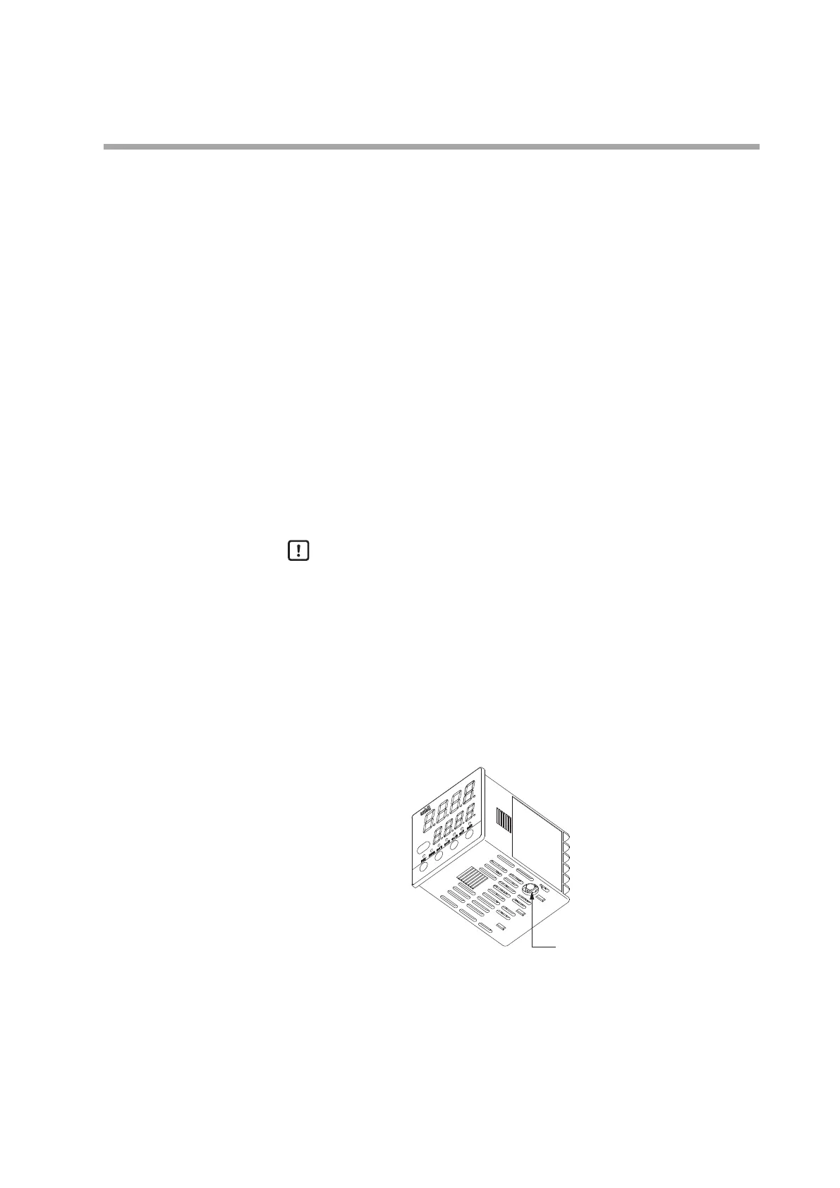
Bottom panel
Loader connector: This connector is connected to a personal computer using the
dedicated cable supplied with the Smart Loader Package.