4-7
Chapter 4. WIRING
Connection with solid state relay (SSR)
To drive the SSR, a model having voltage pulse outputs (V0, VC or VV) must be
used.
Generally, the SSR is classified into two groups, constant current type and resistor
type.
z
Constant current type
The two conditions listed below must be satisfied.
• Input current (maximum): Check that the input current is within the maximum
allowable current or less, then the parallel connection
can be made.
• Operating voltage range: Check that the voltage between the terminals of the
voltage pulse output is within the specified range.
1. Azbil Corporation's PGM10N/PGM10F series
This example shows the calculation for the connection of the SDC15 and the
PGM10N015.
(Note: For connection with other model number, check the specifications of each
model.)
• Input current: Since the input current is 10 mA or less, up to two
units (10mA × 2 = 20 mA < 24 mA [maximum
allowable current]) can be connected in parallel.
• Operating voltage range (input): The rating voltage is 3.5 to 30 V DC. Therefore,
the voltage between the terminals is within the
range.
Voltage between terminals (two PGM10N units)
= Open voltage - internal resistance × total drive current
= 19 V DC ±15 % - 82 Ω ±0.5 % × 20 mA
15 to 20 V
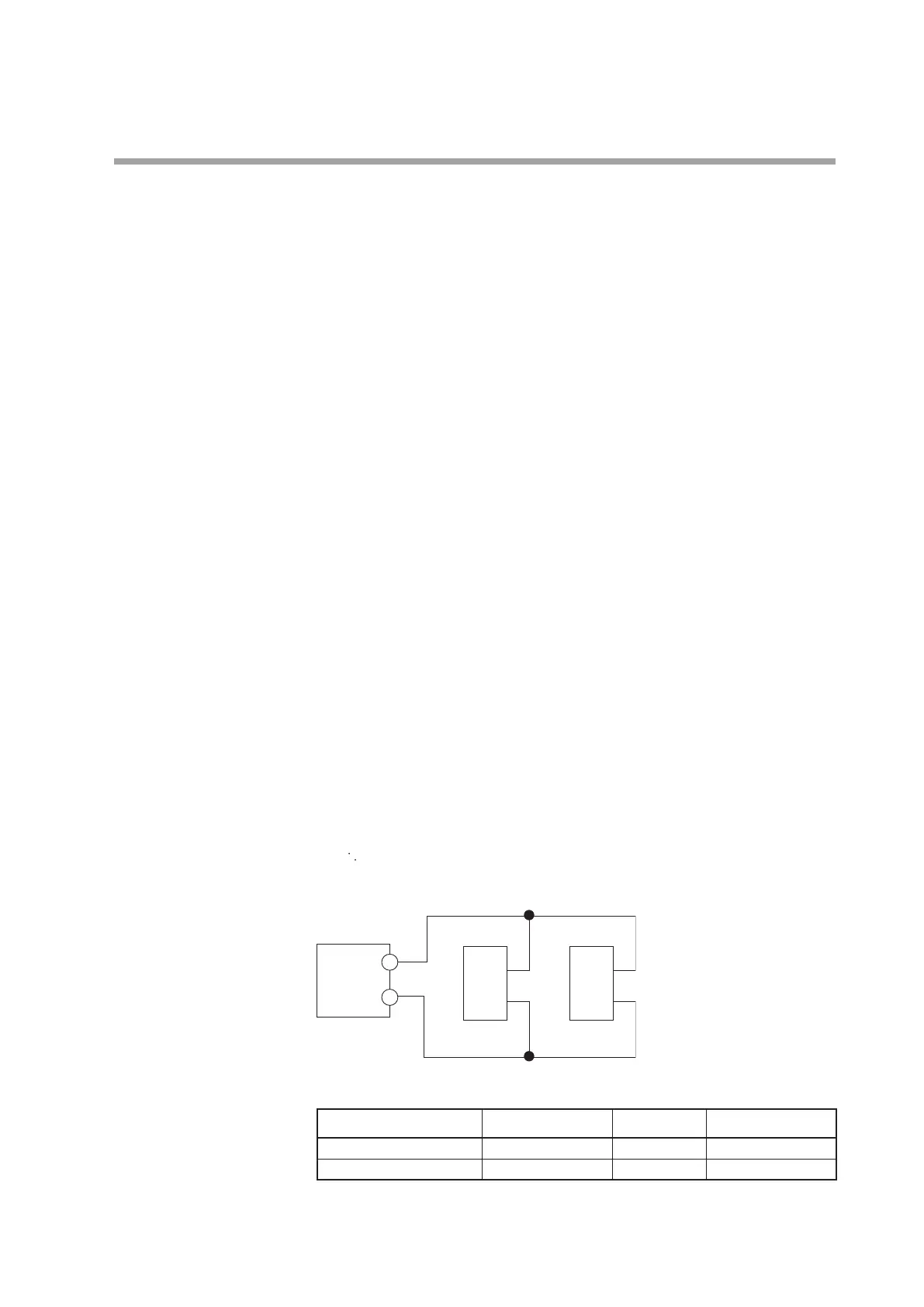
Connection diagram
This unit
+
–
+
–
PGM10N/PGM10F
+
–
PGM10N/PGM10F
Number of connectable units
SSR to be used Connection V0/VC model VV model
PGM10N Parallel connection Up to 2 units Up to 4 units*
PGM10F Parallel connection Up to 2 units Up to 4 units*
*
2 units for each output