4-9
Chapter 4. WIRING
z
Resistor type (Azbil Corporation's PGM_ _ 2A1, etc.)
When necessary, an appropriate external resistor is connected in series so that the
voltage between the input terminals of the SSR you are using is within the specified
range.
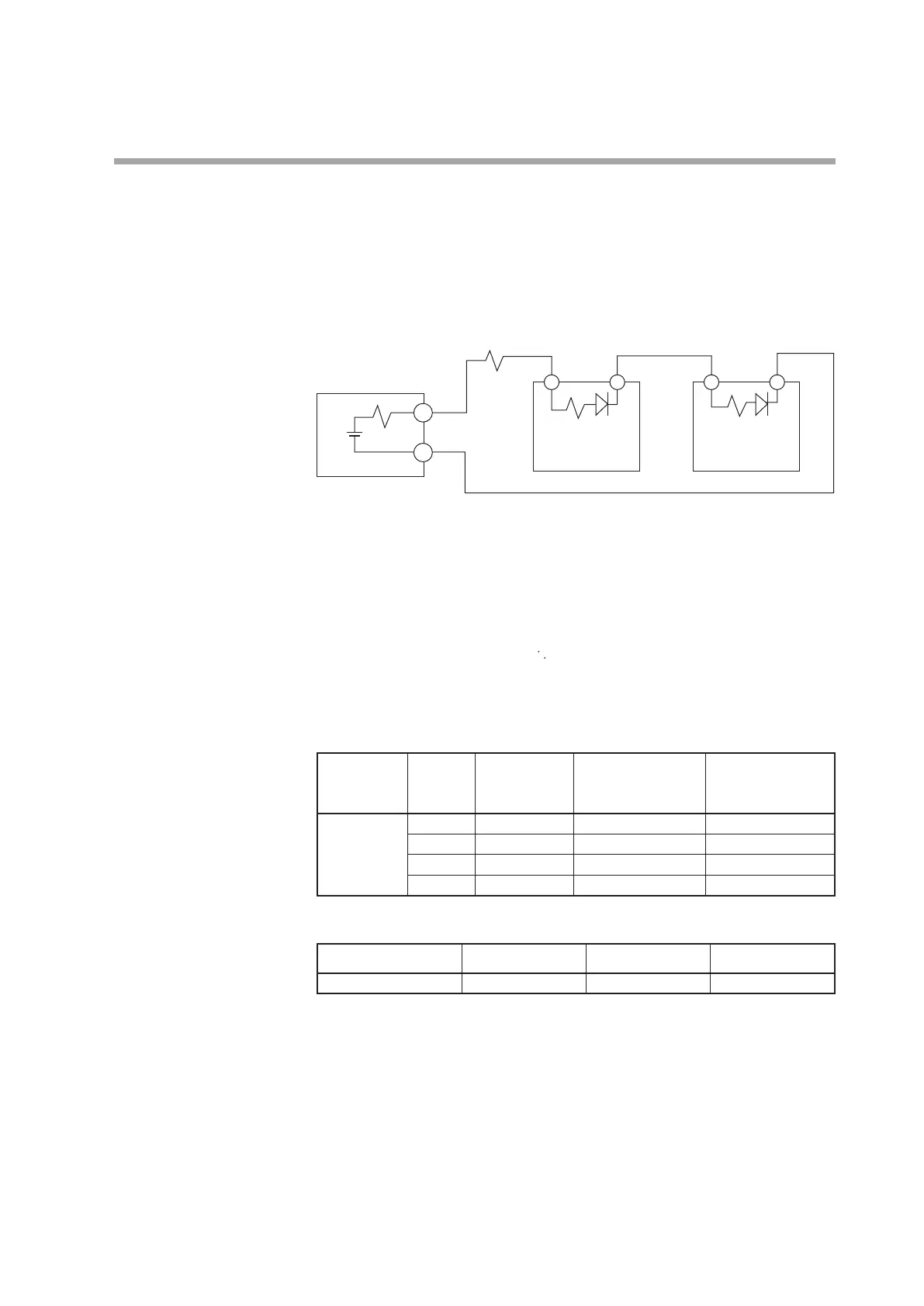
(Example) Connection of two Azbil Corporation PGM units
Connection diagram
This unit
V
R0
PGM_ _2A1
R2 Vf
3 4
PGM_ _2A1
R2 Vf
3 4
+
-
V: 19 V ± 15%
R0: 82 Ω ± 0.5%
R1: 680 Ω
R2: 260 Ω
Vf: 1.1 V
Voltage between terminals of PGM = (V - 2 × Vf) / (R0 + R1+ R2 + R2) × R2 + Vf
4.5 V
Input voltage range of PGM: Since the input voltage range is 3 to 6 V, the
operation is possible.
External resistors
SSR to be used Number of
units to be
connected
Connection External
resistor
Not
es
PGM_ _2A1
1 – 1kΩ (serial connection)
Rating is 1/2W or more.
2
Serial connection 680Ω (serial connection) Rating is 1/2W or more.
3
Serial connection 330Ω (serial connection) Rating is 1/2W or more.
4
Serial connection
None
Number of connectable units
SSR to be used Connection V0/VC model VV model
PGM_ _2A1 Serial connection Up to 4 units Up to 8 units*
* 4 units for each output