3-8
Chapter 3. MOUNTING AND WIRING
z
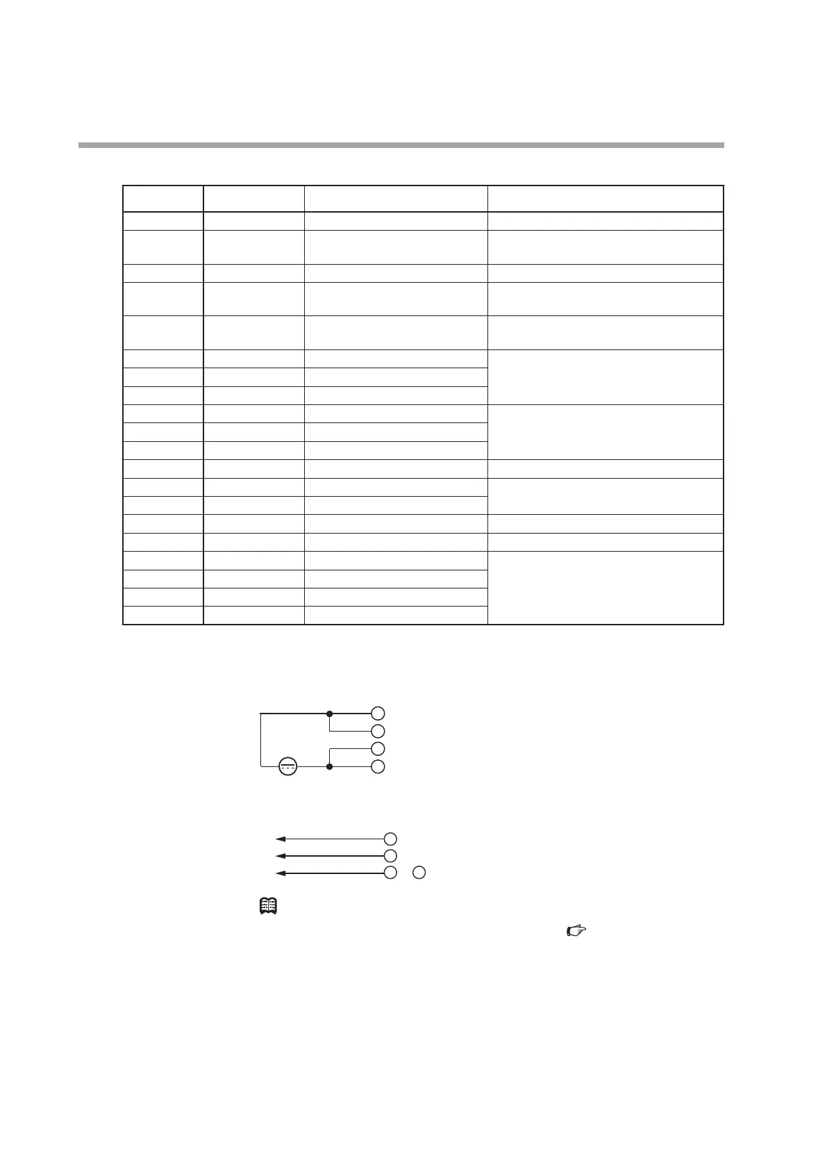
Connector signal names
Pin number Signal name Description Remarks
20 +5 V (5 mA max.) 5 V DC reference voltage outputa 5 mA max.
19 FLOW OUT Instantaneous flow rate (PV) or
flow rate setpoint (SP) output
0 to 5 V/1 to 5 V/0 to 20 mA/ 4 to 20 mA
output
18 A.GND Analog ground Analog signal common
17 FLOW SP INPUT Setpoint flow rate (SP) voltage
input
0 to 5 V/1 to 5 V/0 to 20 mA/ 4 to 20 mA
input
16 MODE INPUT External 3-way switching input 3-stage switching input
(OPEN/GND/5 V)
15 DI3 External contact input 3 2-stage switching input
(OPEN/GND)
14 DI2 External contact input 2
13 DI1 External contact input 1
12 EV2 OUT Event output 2 Open collector non-insulated output
11 EV1 OUT Event output 1
10 ALM OUT Alarm output
9 D.GND Digital ground Digital signal common
8 DB RS-485 communications DB Do not connect on models without the
communications function.
7 DA RS-485 communications DA
6 D.GND Digital ground Digital signal common
5 TEST For test Do not use.
4 POWER GND Power supply ground Connect two wires each in parallel to the
power supply to reduce voltage drop
caused by wiring resistance.
3 POWER GND Power supply ground
2 POWER (24 V) Power supply + (24 V DC)
1 POWER (24 V) Power supply + (24 V DC)
z
Wiring
• Power supply
3
2
1
+-
POWER GND
• RS-485 communications (for models with optional RS-485 only)
DA
7
Note
•
For details on wiring for RS-485 communication, Digital Mass Flow
Controller User's Manual: Communications, CP-SP-1197E.