5-3
Chapter 5. ADVANCED OPERATION
Function setup items
The following table shows the function setup items:
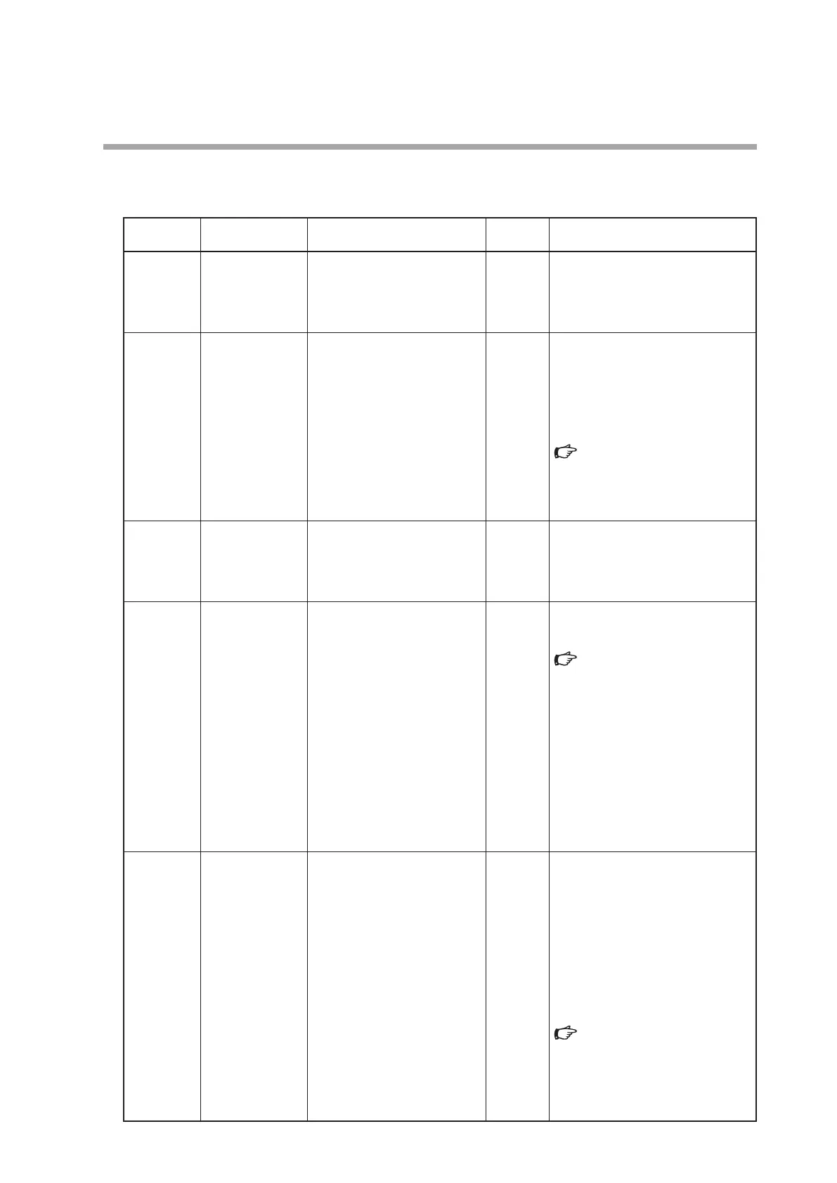
Display Item Item Description Setup Item and Description
Factory
Setting
Remarks
C-01
Key lock 0: Key lock disabled
1: Settings other than flow rate
setting (SP) are key-locked
2: All settings are key-locked
0 The key lock can be cancelled even
while it is enabled.
When an attempt is made to change
a key-locked setting, LOc. is indicated
on the display.
C-02
RUN key operation
and operation
mode selection
when power
turned ON
0: RUN key disabled (Operation
starts in the control mode
when the power is turned ON)
1: RUN key enabled (1)
(Operation is started up in the
operating mode used before
power shutdown when the
power is turned ON)
2: RUN key enabled (2)
(Operation is started up in the
fully closed mode when the
power is turned ON)
1 Determines whether or not the
operating mode is changed (fully
closed/control/fully open) by the RUN
key. Additionally, the operating mode
at power ON can be selected.
For how to select the operating
mode:
4 - 3 Selecting the Operating
Mode (P.4-10).
C-03
Flow rate setup
method
(SP setup method
selection)
0: Digital setup (set
by key operation or
communications)
1: Analog setup (set by external
analog input voltage)
0
*1
C-04
Number of flow
set value
(number of SPs
selection)
0: Number of SPs = 1
(SP-0 only)
1: Number of SPs = 2
(SP-0, SP-1)
2: Number of SPs = 3
(SP-0 to SP-2)
3: Number of SPs = 4
(SP-0 to SP-3)
4: Number of SPs = 5
(SP-0 to SP-4)
5: Number of SPs = 6
(SP-0 to SP-5)
6: Number of SPs = 7
(SP-0 to SP-6)
7: Number of SPs = 8
(SP-0 to SP-7)
0 How to switch the SP number using
external contact input and external
3-way switching input:
Multi-setup (P.4-5).
C-05
Input range
selection of
analog setup
(analog SP input
range selection)
(1) Analog output selection is
set at voltage output
(C-06 = 0, 1, 4, or 5).
0: 0 to 5 V internal reference
input
1: 0 to 5 V external reference
input
2: 1 to 5 V external reference
input
(2) Analog output selection is
set at current output
(C-06 = 2, 3, 6, or 7)
0: 0 to 20 mA external reference
input
1: 0 to 20 mA external reference
input
2: 4 to 20 mA external reference
input
1 Internal reference 0 to 5 V input is
the setting to use the 5 V-reference
voltage from this device when
inputting a voltage with the optional
potentiometer (variable change
resistor with dial). Using this method,
no external power supply for setup is
needed.
The voltage input/current input is
automatically selected as it is linked
with the set value of C-06:
Table in Note
*2
(P.5-9).
*2
,
*3