MN1957 Input / Output 4-15
www.baldormotion.com
4.4.3 Encoder inputs 0-4
Five incremental encoders may be connected to NextMove ESB-2, each with
complementary A, B and Z channel inputs. Each input channel uses a MAX3095 differential
line receiver with pull up resistors and terminators. Encoders must provide RS422 differential
signals. The use of individually shielded twisted pair cable is recommended. A 5 V (±5%),
250 mA supply is provided on each connector for powering the encoder. The same 5 V
supply is also present on connectors X2 and X3 for powering external circuits (see sections
4.4.1 and 4.4.2). Ensure that the total combined current demand of all 5 V outputs does not
exceed 1.85 A.
Encoder inputs ENC 0 - ENC 3 can be read and controlled with a range of Mint keywords
beginning with ENCODER... . When using these keywords, the encoder’s number is used
as the channel parameter. For example, Print ENCODER(2) reads the ENC 2 input.
Encoder input ENC 4 can be read and controlled with a range of Mint keywords
beginning with AUXENCODER... . When its position has been latched by a fast interrupt
(see section 4.3.1.1) it can also be controlled using Mint keywords beginning with
FASTAUX... . When using the AUXENCODER... or FASTAUX... keywords, the channel
parameter 1 is used (i.e. auxiliary encoder channel 1). For example,
Print FASTAUXENCODER(1) reads the latched value read from ENC 4. Note that
auxiliary encoder channel 0 is used to reference the auxiliary encoder input formed by
digital inputs DIN17 - DIN19 (see section 4.3.1.4).
Figure 20: Encoder inputs - keyword and channel summary
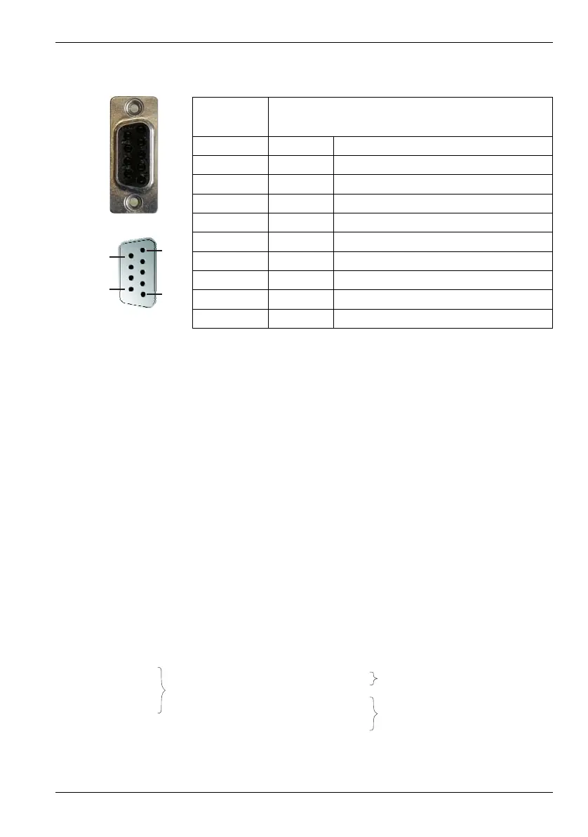
Location X5, X6, X7, X14, X15
Mating connectors: 9-pin male D-type
Pin Name Description
1 CHA+ Channel A signal
2 CHB+ Channel B signal
3 CHZ+ Index channel signal
4 Shield Shield connection
5 GND Digital ground
6 CHA- Channel A signal complement
7 CHB- Channel A signal complement
8 CHZ- Index channel signal complement
9 +5 V out Power supply to encoder
ENC 0
ENC 1
ENC 2
ENC 3
DIN17
DIN18
DIN19
ENC 4
Print ENCODER(0)
Print ENCODER(1)
Print ENCODER(2)
Print ENCODER(3)
Print AUXENCODER(1)
Print FASTAUXENCODER(1)
Print AUXENCODER(0)
Input InputExampleExample
Servo Systems Co. • 115 Main Road • P.O. Box 97 • Montville, NJ,
07045-0097 • (973) 335-1007 • Toll Free: (800) 922-1103
Fax: (973) 335-1661 • www.servosystems.com