Customizing Your Application 8-3MN762
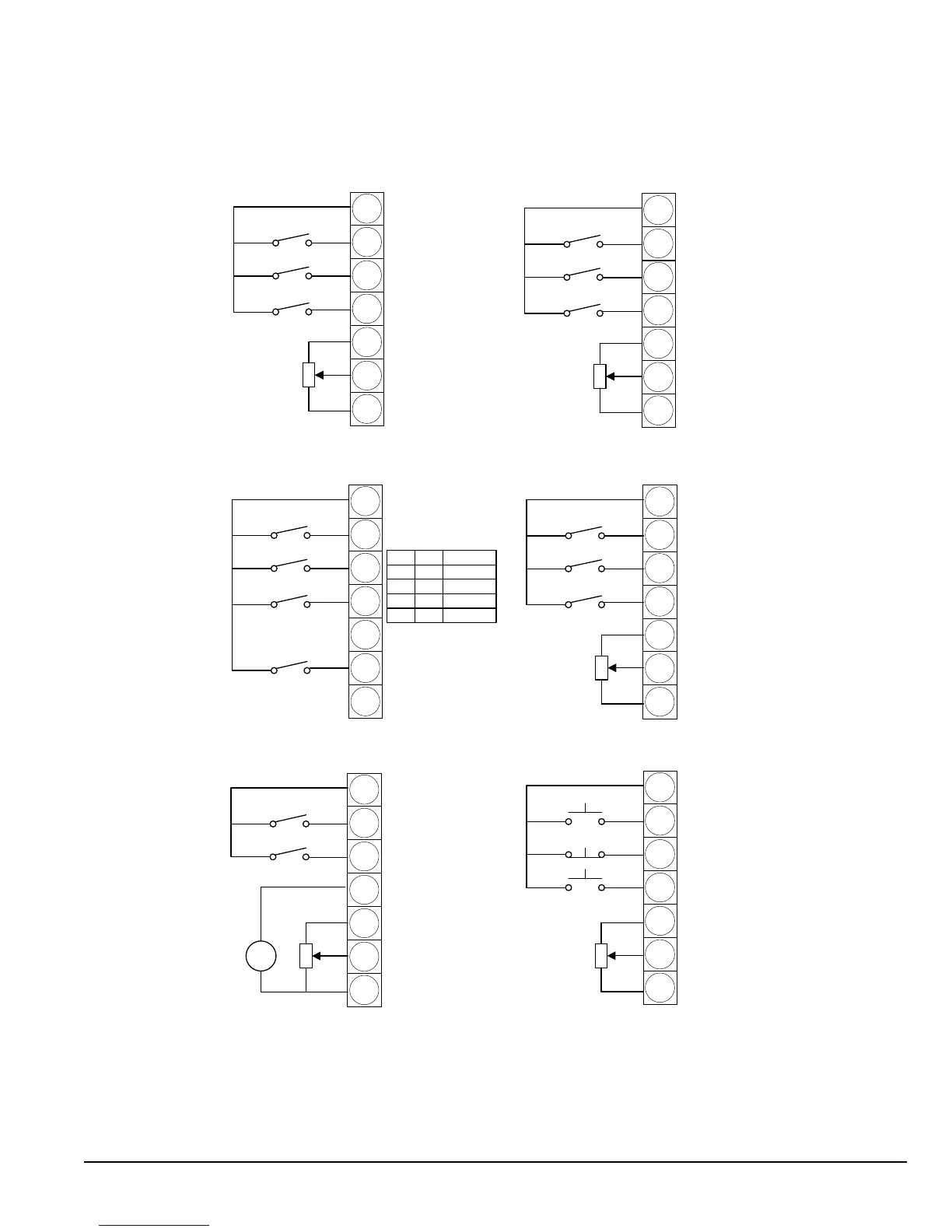
Figure 8-1 Terminal Mode Example Wiring
1
2
3
4
5
6
7
1
2
3
4
5
6
7
1
2
3
4
5
6
7
T3 T4
0 0
1 0
0 1
1 1
Speed
Preset 1
Preset 2
Preset 3
Preset 4
1
2
3
4
5
6
7
1
2
3
4
5
6
7
+
-
1
2
3
4
5
6
7
Terminal mode P07 = 0, P08 = 0
Terminal mode P07 = 0, P08 = 1
Terminal mode P07 = 0, P08 = 2 Terminal mode P07 = 0, P08 = 3
+24V Output
O: Stop (disable)
C: Run (enable)
O: Forward
C: Reverse
O: Analog Speed Ref
C: Preset Speed 1
+10V Output
Analog Speed Ref
0V
+24V Output
O: Stop (disable)
C: Run (enable)
O: Analog Speed Ref
C: Preset Speed 1/2
O: Preset Speed 1
C: Preset Speed 2
+10V Output
Analog Speed Ref
0V
+24V Output+24V Output
+24V Output
+24V Output
O: Stop (disable)
C: Run (enable)
O: Stop (disable)
C: Run (enable)
O: Analog Speed Ref
C: Preset Speed 1
+10V Output
+10V Output
Analog Speed Ref
0V
0V
O: Preset Speeds 1-4
C: Max Speed (P06)
Volts/
Current
(P44)
Terminal mode P07 = 0, P08 = 4
Terminal mode P07 = 0, P08 = 11
O: Stop (disable)
C: Run (enable)
O: External Trip
C: Run Permit
C: Run Forward
O: Stop
C: Run Reverse
O: Local Speed Ref
C: Remote Speed Ref
Remote Speed Ref
(Analog In 2)
+10V Output
Local Analog Ref
(Analog In 1)
0V
+10V Output
Analog Speed Ref
0V