www.balluff.com 11english
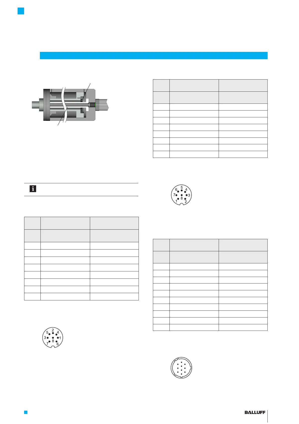
Fig. 4-8: Example2, transducer installed with supporting rod
4.4 Electrical connection
Depending on the model, the electrical connection is made
using a cable or a connector.
The connection or pin assignments for the respective
version can be found in Tab. 4-2 to Tab. 4-6.
Note the information on shielding and cable
routing on page12.
4.4.1 Connector type S32
BTL7 standard BTL7 USB
configurable
Pin BTL7-S5_ _-…-S32
BTL7-S5_ _B-…-S32
BTL7-S510-…-S32
BTL7-S510B-…-S32
1 +Clk +Clk
2 +Data +Data
3 –Clk –Clk
4 Not used
1)
La
2)
5 –Data –Data
6 GND GND
7 10…30V 10…30V
8 Not used
1)
Lb
2)
1)
Unassigned leads can be connected to the GND on the controller side
but not to the shield.
2)
Communication line
Tab. 4-2: Connection assignment BTL7…-S32
Fig. 4-9:
Pin assignment of S32 (view of connector pins of
transducer), 8-pin M16 circular plug
4.4.2 Connector type S115
BTL7 standard BTL7 USB
configurable
Pin BTL7-S5_ _-…-S115
BTL7-S5_ _B-…-S115
BTL7-S510-…-S115
BTL7-S510B-…-S115
1 +Clk +Clk
2 +Data +Data
3 –Clk –Clk
4 Not used
1)
La
2)
5 –Data –Data
6 GND GND
7 10…30V 10…30V
8 Not used
1)
Lb
2)
1)
Unassigned leads can be connected to the GND on the controller side
but not to the shield.
2)
Communication line
Tab. 4-3: Connection assignment BTL7…-S115
Fig. 4-10:
Pin assignment of S115 (view of connector pins of
transducer), 8-pin M12 circular plug
4.4.3 Connector type S140
BTL7 standard BTL7 USB
configurable
Pin BTL7-S5_ _-…-S140
BTL7-S5_ _B-…-S140
BTL7-S510-…-S140
BTL7-S510B-…-S140
A +Data +Data
B +Clk +Clk
C –Clk –Clk
D 10…30V 10…30V
E Not used
1)
Not used
1)
F GND GND
G Not used
1)
La
2)
H Not used
1)
Lb
2)
J –Data –Data
K Not used
1)
Not used
1)
1)
Unassigned leads can be connected to the GND on the controller side
but not to the shield.
2)
Communication line
Tab. 4-4: Connection assignment BTL7…-S140
Fig. 4-11:
Pin assignment of S140 (view of connector pins of
transducer), 10-pin circular plug
4
Installation and connection (continued)
Magnet
(e.g. BTL-P-1028-15R)
Supporting rod made of non-magnetizable material
BTL7-S5 __ (B)-M ____ -A/B/Y/Z(8)-S32/S115/S140/S147/KA __ /FA __
Micropulse Transducer - Rod Style

 Loading...


