8 english
3
Construction and function (continued)
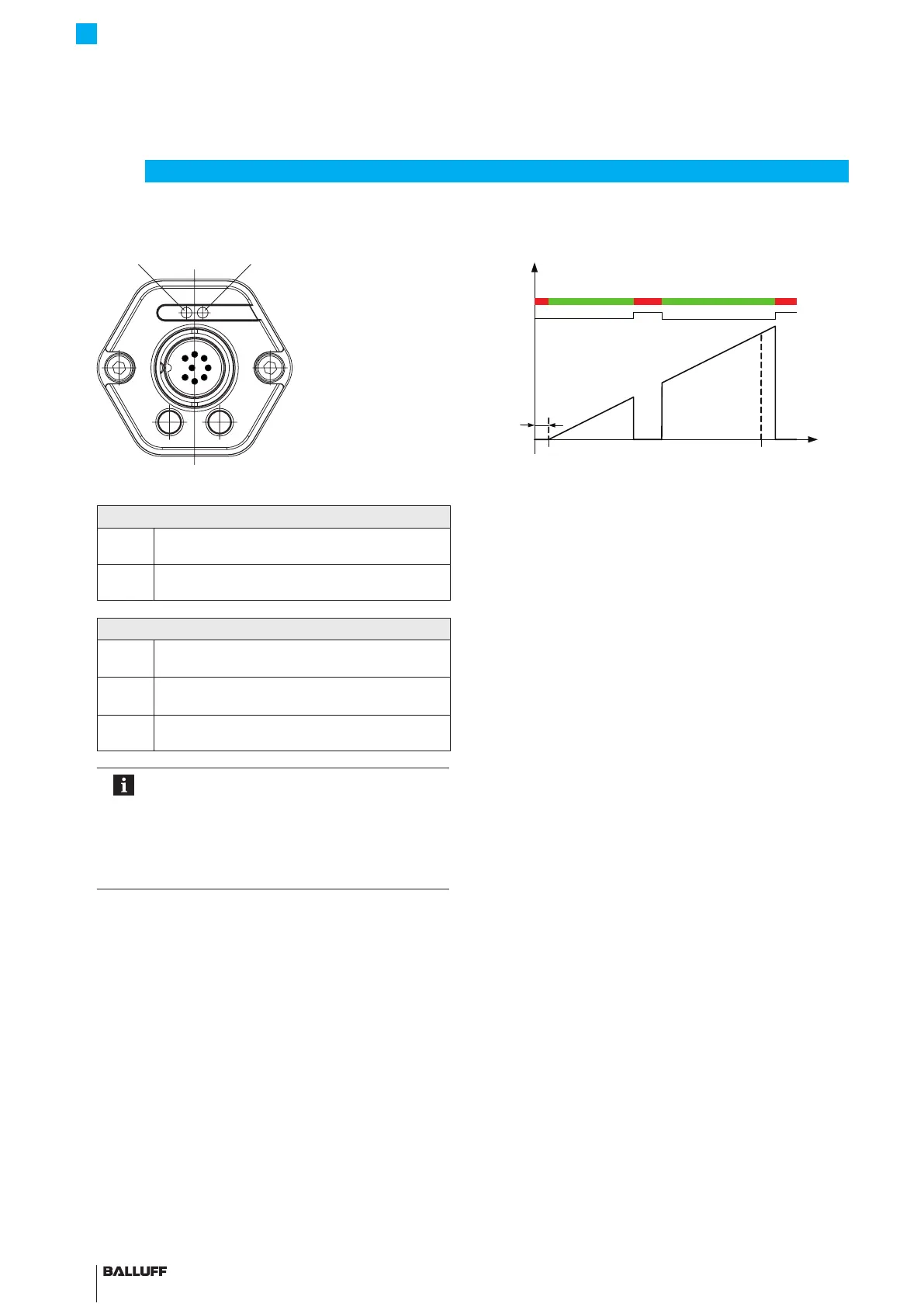
3.3 LED display
Fig. 3-2:
Position of the BTL7 LED displays
LED1
Green Normal function
Magnet is within the limits.
Red Error
No magnet or magnet outside the limits.
LED2
Green
Synchronous operation
1)
Internal measurement is synchronous to SSI query.
Off
Asynchronous operation
1)
Internal measurement is asynchronous to SSI query.
Flashing
green
Programming mode
Only with BTL7-S510(B)-…
Note on configuration
(only BTL7-S510(B)-…)
The entire range of functionality can only be
configured with the PC software "Micropulse
Configuration Tool". To do this, the USB
communication box must be connected
(see Accessories on page23).
When reading or writing data via the Micropulse
Configuration Tool, LED2 flashes green to display
programming mode.
1) Asynchronous operation is reached when the external sampling rate is
>f
A,max
or <62.5Hz (only with BTL7-S5_ _B-…), see Technical data on
page20, Fig. 8-1.
Behavior of LED1 and the error value through the entire
range:
Fig. 3-3:
Pos
SSI
out
0
≈5 mm
2
21
LED
Behavior of LED1 and error value BTL7≥5µm
For resolutions ≥5µm, in the case of an error, bit 2
21
is
set. For resolutions <5µm, there is no error bit and the
value 0 is output.
Nullpoint End point
Magnet
missing
BTL7-S5 __ (B)-M ____ -A/B/Y/Z(8)-S32/S115/S140/S147/KA __ /FA __
Micropulse Transducer - Rod Style

 Loading...


