www.balluff.com 15english
6
SSI interface (continued)
6.2 Data formats
Standard BTL7 has the following factory settings for
position output, which can no longer be changed
retroactively:
– SSI24, SSI25 or SSI26
– Binary or Gray coded
– Rising or falling
The contents of the information to be transferred and the
error value can be configured with the BTL7-S510(B)-….
Position, speed, or position/speed differences can be sent
via Data. The MSB is always transmitted first.
23 Position 0
M L
Output of a position via SSI24
M = MSB (Most Significant Bit)
L = LSB (Least Significant Bit)
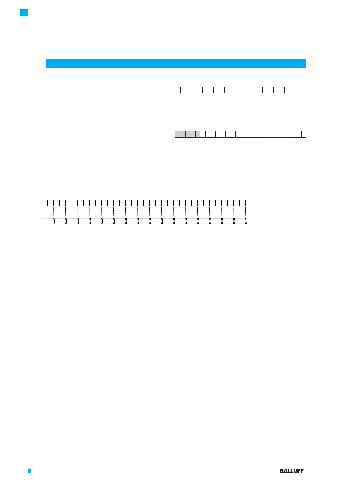
25 2423 22 21 20 Error value or position value 0
0 0 0 0 1 0 0 0 0 0 0 0 0 0 0 0 0 0 0 0 0 0 0 0 0 0
Example of a SSI26 with error bit at bit position21 and
error value0. The data length there is 21bit, the total bit
number is 26. Four zeros are transmitted before the error
bit.
k
ta
15
1234 5
14 13 12
678 9 10 11 12 13 14 15 16 17
11 10 9 87 6 543210
MSB LSB
Fig. 6-1: Example of a complete SSI16 data transmission
Depending on the configuration, position or speed data
may have a leading sign with the BTL7-S510(B)-….
Negative values are output as a two's complement. With
positive speeds, the magnet moves away from the
electronics head; with negative speeds it moves towards
the electronics head. The controller must be set to process
signed data then.
6.3 Faulty SSI query
Underclocking
If there are too few clock edges, the current data level will
be maintained for the timet
o
(t
o
=2·T
Clk
Timeout times)
after the last negative edge from Clk. If, however, another
positive edge occurs, the next bit will then be output.
Afterwards, a T
o
event will occur internally, the data output
switches to low and then back to high after the time t
m
has
elapsed. The high level is maintained until the next clock
burst. Timet
m
starts after the end of timet
o
.
Overclocking
If there are too many clock edges, the data output will
switch to low after the correct number of cycles has been
completed. The t
m
timer is started again for every
additional negative edge from Clk and the T
m
event is set
internally. Data switches back to high after the timet
m
has
elapsed.
A T
o
or T
m
event is displayed in the status field as a com-
munication error in the Micropulse Configuration Tool. In
short, a communication error is caused by the following:
– The bit number set in the transducer does not
correspond to the bit number in the controller.
n
BTL
>n
PLC
T
o
event
n
BTL
<n
PLC
T
m
event
– The SSI clock frequency is too low
f
Clk
<9.771kHzT
o
event
– The pause between two clock packages is too short
T
m
event
BTL7-S5 __ (B)-M ____ -A/B/Y/Z(8)-S32/S115/S140/S147/KA __ /FA __
Micropulse Transducer - Rod Style
 Loading...


