www.balluff.com 17english
7
Configuration using the Micropulse Configuration Tool (only for BTL7-S510(B)-…)
7.1 Micropulse Configuration Tool (software)
The BTL7-S510(B)-… transducer can be configured
quickly and simply on a PC using the Micropulse
Configuration Tool PC software.
The most important features include:
– Online display of the current position of the magnet
– Graphic support for setting the functions and
characteristics
– Display of information on the connected transducer
– Selection of displayed number formats and units
– Possible to reset to the factory settings
– Demo mode without a connected transducer
The PC software and associated manual can
be found in the Internet under
www.balluff.com.
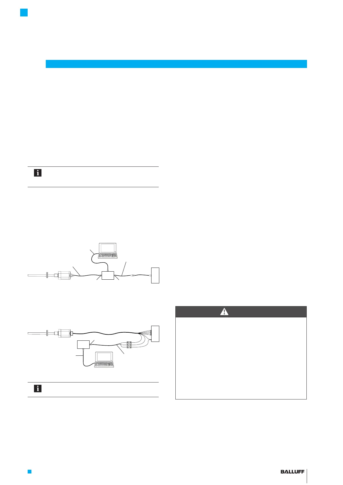
7.2 Connecting the USB communication box
With BTL7-S510(B)-… transducers with a connector (S32/
S115/S140), the communication box must be looped in
between the transducer and controller. The communication
box is connected to the PC via a USB cable.
Fig. 7-1: Connecting the communication box with connector
With a BTL7-S510(B)-…-cable transducer, the
communication lines La, Lb and GND are connected to the
USB communication box.
Fig. 7-2: Connecting the communication box with a cable connection
When reading or writing data via the
Configuration Tool, the LED2 flashes green.
7.3 Configuration options
Prerequisites
– USB communication box connected to the transducer
and PC.
– Software correctly installed.
– Transducer connected to the power supply.
– Magnet on transducer.
Output functions
– Position: Position in the measuring range.
– Speed: Speed of the magnet; the sign indicates the
direction of movement. A movement from the starting
point to end point is output with a positive sign; a
movement from the end point to the starting point is
output with a negative sign.
– Speed (unsigned): Speed of the magnet, the direction
of movement cannot be read.
– Differential position: Distance between two magnets.
Selection is only possible if two magnets have been
selected.
– Speed difference: The speeds of two magnets are
subtracted to form a sum. Selection is only possible if
two magnets have been selected.
Freely configurable characteristic curve
– The gradient of the characteristic curve can be set by
adjusting the resolution.
– The limits can be adjusted to the measuring range.
– The error value can be set.
Boundary conditions for several magnets
– Two magnets can only be selected from a nominal
length ≥90 mm.
– The distance between two magnets must be ≥65 mm.
DANGER
Uncontrolled system movement
When starting up, if the position measuring system is
part of a closed loop system whose parameters have not
yet been set, the system may perform uncontrolled
movements. This could result in personal injury and
equipment damage.
► The system must be taken out of operation before
configuration.
► Transducers may only be connected to the
communication box for configuration.
► The communication box must be removed after
configuration.
USB cable
6-pin8-pin
Connection cable approx. 0.3 m
with connector (socket)
Connection cable
approx. 0.3 m with
connector (plug)
Controller
8-pin
USB cable
Controller
Connection cable
approx. 0.6 m with
luster terminal
BTL7-S5 __ (B)-M ____ -A/B/Y/Z(8)-S32/S115/S140/S147/KA __ /FA __
Micropulse Transducer - Rod Style

 Loading...


