www.balluff.com 3english
BTL7-A/C/E/G_ _ _-M_ _ _ _-A/B/Y/Z(8)-S32/S115/S135/S140/KA_ _/FA_ _
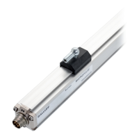
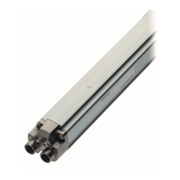
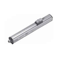
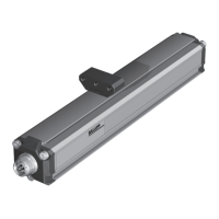
Micropulse Transducer - Rod Style
1
Notes to the user 5
1.1 Validity 5
1.2 Symbols and conventions 5
1.3 Scope of delivery 5
1.4 Approvals and markings 5
2
Safety 6
2.1 Intended use 6
2.2 General safety notes for the position measuring system 6
2.3 Explanation of the warnings 6
2.4 Disposal 6
3
Construction and function 7
3.1 Construction 7
3.2 Function 8
3.3 LED display 8
4
Installation and connection 9
4.1 Installation guidelines 9
4.2 Preparing for installation 9
4.3 Installing the transducer 10
4.3.1 Installation recommendation for hydraulic cylinders 10
4.4 Electrical connection 11
4.4.1 Connector type S32/cable connection 11
4.4.2 Connector type S115 11
4.4.3 Connector type S135 12
4.4.4 Connector type S140 12
4.5 Shielding and cable routing 13
5
Startup 14
5.1 Starting up the system 14
5.2 Operating notes 14
6
Calibration procedure 15
6.1 Calibration device (not for BTL7-…-S140) 15
6.2 Programming inputs (not for BTL7-…-S135) 15
6.3 Calibration procedure overview 15
6.3.1 Teach-in 15
6.3.2 Adjusting 16
6.3.3 Online setting 16
6.3.4 Reset 16
6.4 Selecting the calibration procedure 16
6.5 Calibration procedure notes 17
 Loading...
