1.18 Use Cases 139
1.18.5.1.2 Functionality
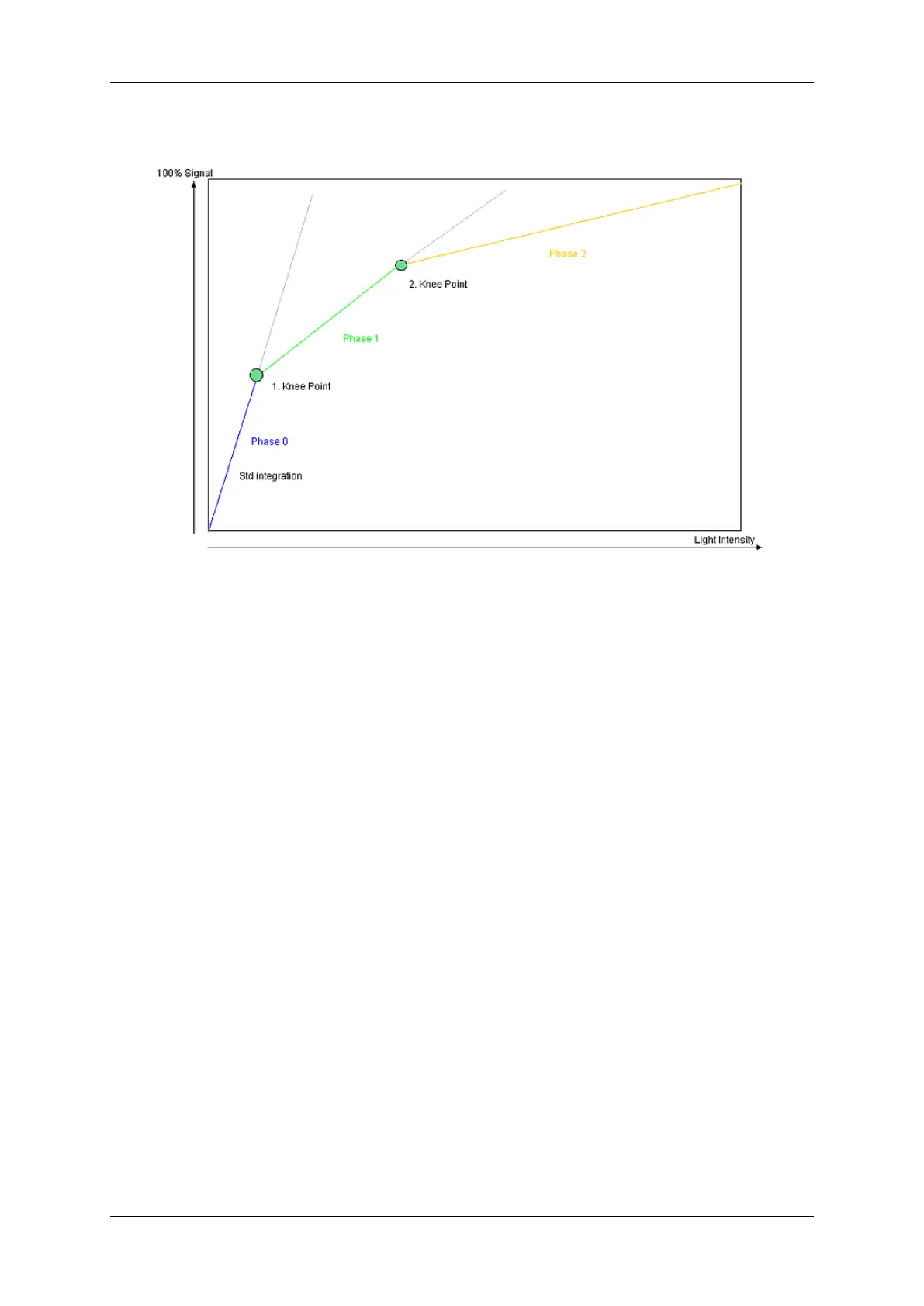
Figure 1: Diagram of the -x00w sensor's HDR mode
1.18.5.1.2.1 Description
• "Phase 0"
– During T1 all pixels are integrated until they reach the defined signal level of Knee Point 1.
– If one pixel reaches the level, the integration will be stopped.
– During T1 no pixel can reached a level higher than P1.
• "Phase 1"
– During T2 all pixels are integrated until they reach the defined signal level of Knee Point 2.
– T2 is always smaller than T1 so that the percentage compared to the total exposure time is lower.
– Thus, the signal increase during T2 is lower as during T1.
– The max. signal level of Knee Point 2 is higher than of Knee Point 1.
• "Phase 2"
– During T2 all pixels are integrated until the possible saturation.
– T3 is always smaller than T2, so that the percentage compared to the total exposure time is again lower
here.
– Thus, the signal increase during T3 is lower as during T2.
For this reason, darker pixels can be integrated during the complete integration time and the sensor reaches its full
sensitivity. Pixels, which are limited at each Knee Points, lose a part of their integration time - even more, if they are
brighter.
MATRIX VISION GmbH