1.9 Technical Data 59
See also
UserDataEntry class description
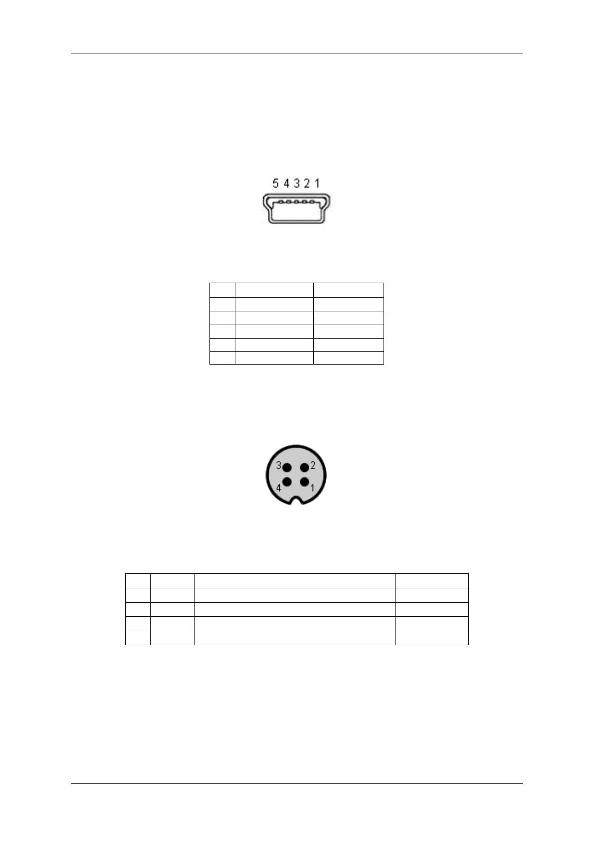
1.9.5.1.1 Mini-B USB (USB 2.0)
Figure 30: Mini-B USB
Pin Signal Comment
1 USBPOWER_IN Supply voltage
2 USB_DATA- Data
3 USB_DATA+ Data
4 ID Not connected
5 GND Ground
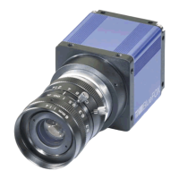
1.9.5.1.2 4-pin circular plug-in connector with lock (I/O)
Figure 31: 4-pin circular plug-in connector (female)
Pin Signal Comment Color (of cable)
1 IN0 + Opto-isolated digital input 0 (Positive voltage) brown
2 IN0 - Opto-isolated digital input 0 (Negative voltage) white
3 OUT0 + Opto-isolated digital output 0 (Positive voltage) blue
4 OUT0 - Opto-isolated digital output 0 (Negative voltage) black
Manufacturer: Binder
Part number: 79-3107-52-04
1.9.5.1.2.1 Electrical characteristic Please have a look at the mvBlueFOX-MLC digital I/O characteristics (opto-
isolated model) of the 12-pin Wire-to-Board Header (USB / Dig I/O) (p. 52).
1.9.5.2 LED states
MATRIX VISION GmbH