50
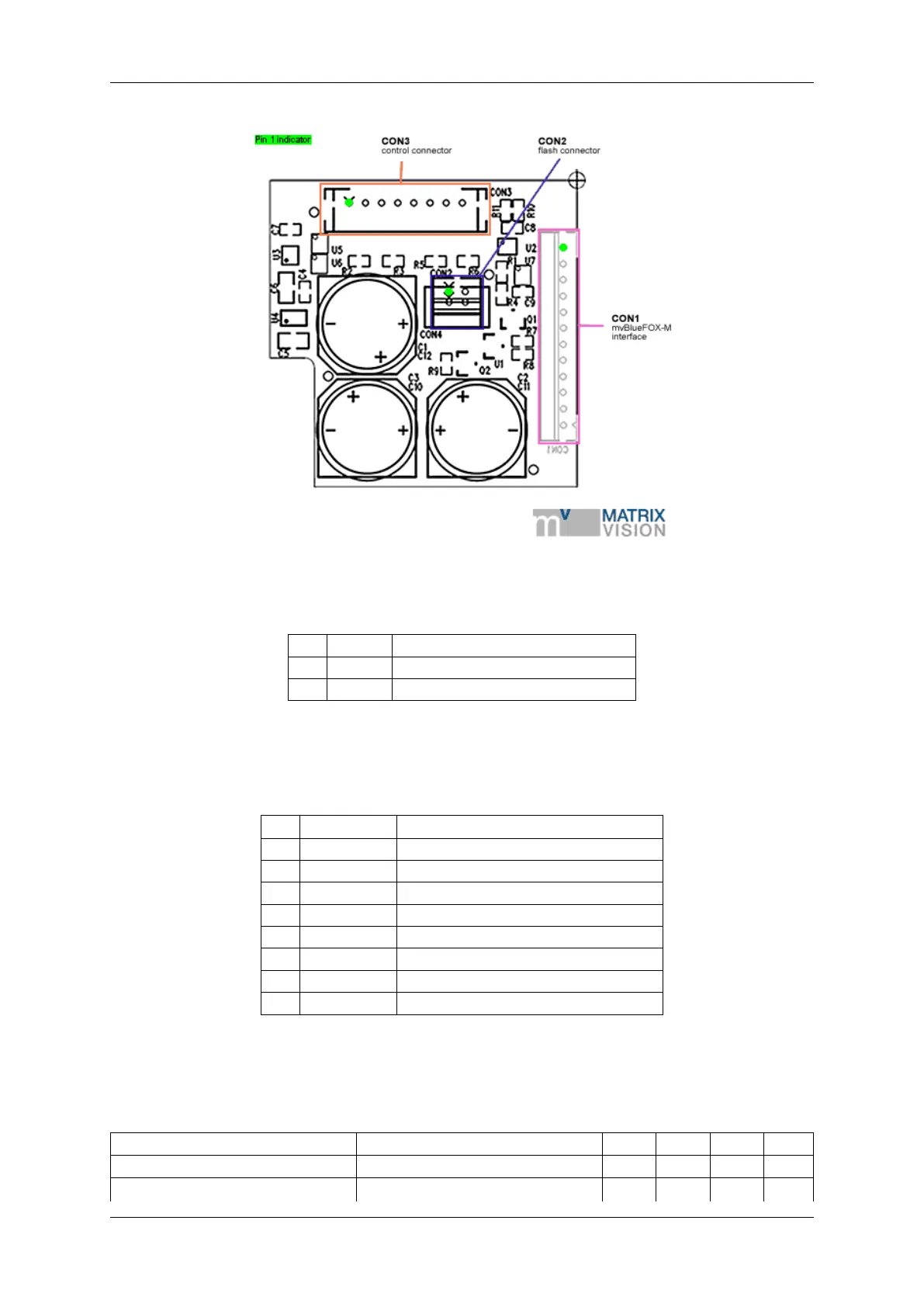
Figure 18: Model 2 with CON1 connector
Pin Signal Comment
1 Flash + Flash power
2 Flash - Switched to ground (low side switch)
1.9.3.4.1.1 CON2 - Flash connector Manufacturer: JST
Part number: B-2B-PH
Pin Signal Comment
1 GND LED2 cathode connector / board ground
2 LED2 output LED2 anode connector1
3 GND LED1 cathode connector / board ground
4 LED1 output LED1 anode connector
5 GND Board ground
6 Input2 Switch to ground for setting Input2
7 GND Board ground
8 Input1 Switch to ground for setting Input1
1.9.3.4.1.2 CON3 - Control connector Manufacturer: JST
Part number: B-8B-PH-SM4 TB
Signal Parameter Min Typ Max Unit
GND Board ground 0 V
LED 1/2 output (anode)
Output voltage
2
5 V
MATRIX VISION GmbH