1.9 Technical Data 53
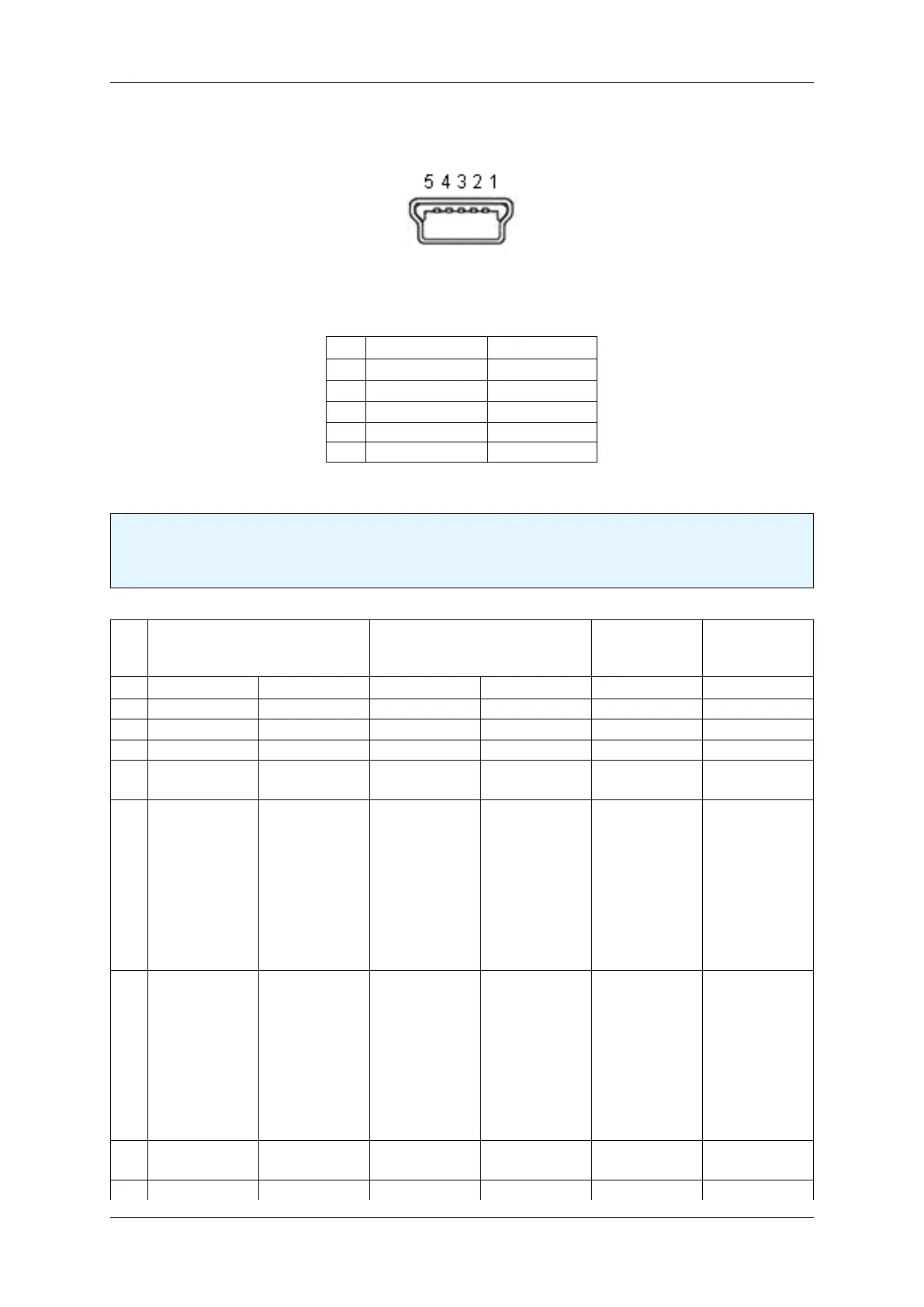
1.9.4.2.2 Mini-B USB (USB 2.0)
Figure 22: Mini-B USB
Pin Signal Comment
1 USBPOWER_IN Supply voltage
2 USB_DATA- Data
3 USB_DATA+ Data
4 ID Not connected
5 GND Ground
1.9.4.2.3 12-pin Wire-to-Board header (USB 2.0 / Dig I/O)
Note
If you have the mvBlueFOX-MLC variant which uses the standard Mini-B USB connector, pin 2 and 3
(USB_DATA+ / USB_DATA-) of the header won't be connected!
pin Opto-isolated variant TTL compliant variant Cable KS-←-
MLC-USB2-←-
IO-W
Cable KS-←-
MLC-IO-W
Signal Comment Signal Comment
1 GND Ground GND Ground GND
2 USB_DATA+ Data USB_DATA+ Data USB_DATA+
3 USB_DATA- Data USB_DATA- Data USB_DATA-
4 USBPOWER←-
_IN
Supply voltage USBPOWER←-
_IN
Supply voltage USBPOWER←-
_IN
5 I2C SDA Serial data
line (the I2C
interface is
master-only,
which means
that I2C slaves
can only be
connected
externally)
I2C SDA Serial data line
6 I2C SCL Serial clock
line (the I2C
interface is
master-only,
which means
that I2C slaves
can only be
connected
externally)
I2C SCL Serial clock
line
7 USBPOWER←-
_IN
Supply voltage USBPOWER←-
_IN
Supply voltage red
8 GND Ground GND Ground black black
MATRIX VISION GmbH
 Loading...