P/N 43298 rev. E 15
Banner Engineering Corp. •Minneapolis,MNU.S.A.
www.bannerengineering.com•Tel:763.544.3164
MINI-ARRAY
®
InstructionManual
Installation and Mechanical Alignment
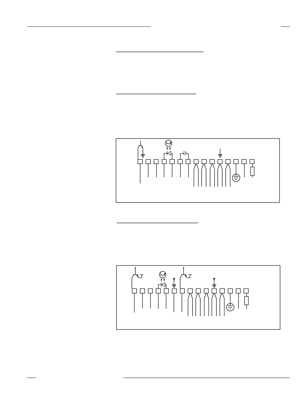
Figure 3-5. Model MAC-1 hookup
1
+
–
+
–
10-30V dc
Gate
16-30V dc
1.2 A Max.
234
5678
9
101112131415
F1
BROWN
BLUE
DRAIN (BARE)
BLACK
WHITE
EMITTER and
RECEIVER CABLES
V– V+
RS485
500 mA
Max.
Out 1
30V
150 mA
Max.
ALARM
Power
3.4 Controller Wiring and Output Hookups
CableclearancedimensionsforthearraysareshowninFigure3-3.
Controllerconnectionsaremadeviathewiringterminalsalongthefrontsurface
ofeachmodule.Emitterandreceiverhookupsandcontrolleroutputsareshownin
Figures3-5through3-11.
3.4.1 Model MAC-1 Controller Hookup
Output 1:Controllerterminals#9and#10(OUT1)arereedrelaycontactsrated
at125Vac/dcmax.,10VAmax.resistive(i.e.,non-inductive)load.Itmaybe
programmedaseithernormallyopenornormallyclosed.
Alarm:Controllerterminal#15(Alarm)isanopen-collectorNPNtransistorswitch
ratedat30Vdcmax.,150mAmax.Itisprotectedagainstoverloadandshortcircuits.
3.4.2 Model MACP-1 Controller Hookup
Output 1:Controllerterminal#9(OUT1)isanopen-collectorPNPtransistorswitch
ratedat30Vdcmax.,150mAmax.Itisprotectedagainstoverloadandshortcircuits.
Alarm:Controllerterminal#15(ALARM)isanopen-collectorPNPtransistorswitch
ratedat30Vdcmax.,150mAmax.Itisprotectedagainstoverloadandshortcircuits.
Bothoutputsarecurrentsourcing.
Figure 3-6. Model MACP-1 hookup
1
+
–
+
–
10-30V dc
Gate
16-30V dc
1.2 A Max.
234
5678
9
101112131415
F1
BROWN
BLUE
DRAIN (BARE)
BLACK
WHITE
EMITTER and
RECEIVER CABLES
V- V+
RS485
Com
30V
150 mA
Max.
ALARM
30V
150 mA
Max.
Out
Power
V+ V+