20 P/N 43298 rev. E
Banner Engineering Corp. •Minneapolis,MNU.S.A.
www.bannerengineering.com•Tel:763.544.3164
MINI-ARRAY
®
InstructionManual
ConfigurationoftheMINI-ARRAYcontrollerisaccomplishedwithaWindows
®
menu-
styleprocedure,usingtheBanner-suppliedsoftwareandaPC-compatiblecomputer
runningWindows
®
XP, Vista, or 7.Aserialdataconnectionismade
betweenthecomputerandtheDB9connectoronthecontroller(seeFigure3-12).
ParameterSetupFiles(PSF)areprogrammedconfigurationsthatcanbestoredinthe
controlmodule’snon-volatilememory.TheBannersoftwarecanstorevariousPSFsin
computerfilesforinstantcall-upofaparticularconfiguration.
TheBannersoftwarealsoprovidestwoadditionalfeatures:AnAlignmentscreenanda
Diagnosticsscreen
5.1 Communications Setup
TheMINI-ARRAYsoftwarepermitsserialcommunicationviaRS-232betweentheMAC
controllerandthePC.TheminimumconnectionstotheDB-9connectoronthe
MINI-ARRAYControllersareasfollows:
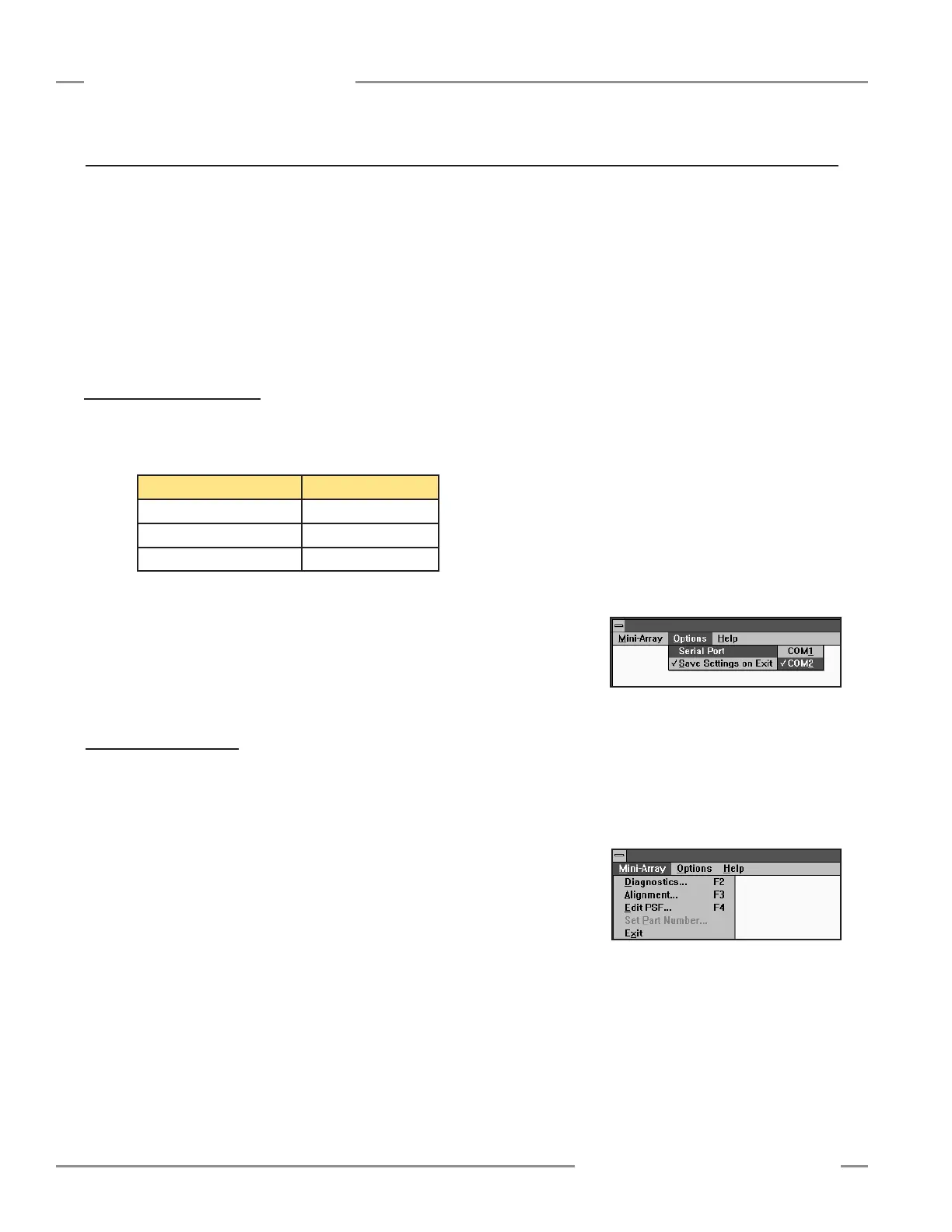
Figure 5-1. MINI-ARRAY software Option
menu
Figure 5-2. MINI-ARRAY software Main
menu
NOTE: DO NOT use a “null modem” RS-232 cable.
ConfiguretheCOMportofthePCbyfirstselectingtheOptionsmenu(seeFigure
5-1).Theprogramsupportsserialcommunicationviathe.COM1-COM20.port.
ofthecomputer.SelectOptions,thenselectSerial Port(orEnter).Selecteither
COM1orCOM2.CheckSave Settings on Exit (ifitisnotalreadychecked)tostore
theCOMportselection.
5.2 Alignment Analysis
AlignmentstatusiscontinuouslydisplayedbythegreenLEDindicatorontheReceiver
andthecontroller.Whenallunblankedbeamsareclear,andexcessgainofallbeams
ismorethan3x,thegreenalignmentindicatorswillbeON.Whentheexcessgain
ofoneormorebeamsdropstobetween3xand1x,thegreenALIGNLEDonthe
controllerwillremainON,buttheyellowLEDonthereceiverwillcomeONtoindicate
awarningofmarginalalignment.SeeSection6formoreinformationaboutsensor
alignment.
OnefeatureoftheMINI-ARRAYsoftwareisaprogramthatdisplaysthestatusof
eachbeaminthearray.Thisroutinecanbeveryhelpfulforfinalalignmentorwhen
analyzinghowtheMINI-ARRAYisviewingobjectsinthesensingarray.Tolaunchthis
program,selectAlignment...undertheMINI-ARRAYmenu(seeFigure5-2),or
presstheF3key.
Controller Configuration
5. Controller Configuration
Pin Number of DB-9 Function
2 Transmit(TX)
3 Receive(RX)
5 Ground(GND)