P/N 43298 rev. E 35
Banner Engineering Corp. •Minneapolis,MNU.S.A.
www.bannerengineering.com•Tel:763.544.3164
MINI-ARRAY
®
InstructionManual
System Operation
6.1 Sensor Operating Status Indicators
NOTE:Statusindicatorsappearto“freeze”ifthecontrollerhasbeenconfiguredforthe
GateortheHostMode(seeSection5.5.6),andthereisnosignaltocausea
scanupdate.
Emitter(Figure6-1)
TheredLEDONindicatesthattheemitterhaspowerappliedandisfunctioning
properly.IftheredLEDisOFF,therehasbeenanemitterfailure.TheredDIAG3
indicatoronthecontrollershouldcomeONwhenevertheredLEDontheemittergoes
OFF.RuntheDiagnosticssoftware(seeSection6.3)todeterminethecauseofthe
emitterfailure.
AflashingredemitterLEDindicatesthattheemitterhasmomentarilylostandthen
regainedpower,andiswaitingforactivityfromthecontroller.ThiscanoccurinGate
orHostModeaftertheemitterhasbeentemporarilyunpluggedandthenreconnected,
butbeforetheemitterreceivesitsnextgatingcommand.
Receiver(Figure6-1)
Thegreen LED ON(only)indicatesproperalignment,andnobeamsbroken.
A flashing green(only)indicatorhasthesamemeaningasaflashingredemitter
indicator,asdescribedabove.
Green and yellow ON togetherindicatesmarginalalignment.TheMINI-ARRAY
Systemwillcontinuetooperatenormally,buttheyellowcomesONasanearly
warningofpossiblesignallossduetogradualsensormisalignmentand/ordirtbuildup
onthelenses,etc.
Thered LED ON(only)indicateseitheroneormorebeamsblockedorsensor
misalignment(ifthescreenisclearofobjects).
All three LEDs (yellow, red and green) ONatthesametimeindicatesareceiver
failure.RuntheDiagnosticssoftware(seeSection6.3)todeterminethecauseofthe
receiverfailure.
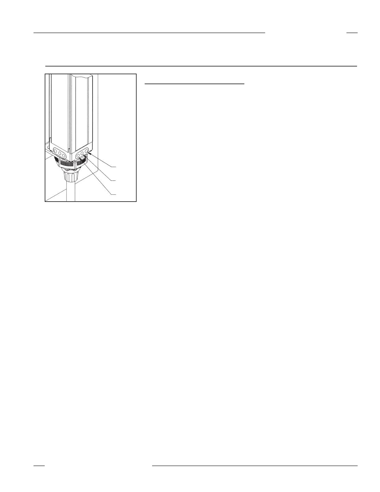
Figure 6-1. MINI-ARRAY sensor status
indicator LEDs
6. System Operation
Green
Red
Yellow