P/N 43298 rev. E 17
Banner Engineering Corp. •Minneapolis,MNU.S.A.
www.bannerengineering.com•Tel:763.544.3164
MINI-ARRAY
®
InstructionManual
Installation and Alignment
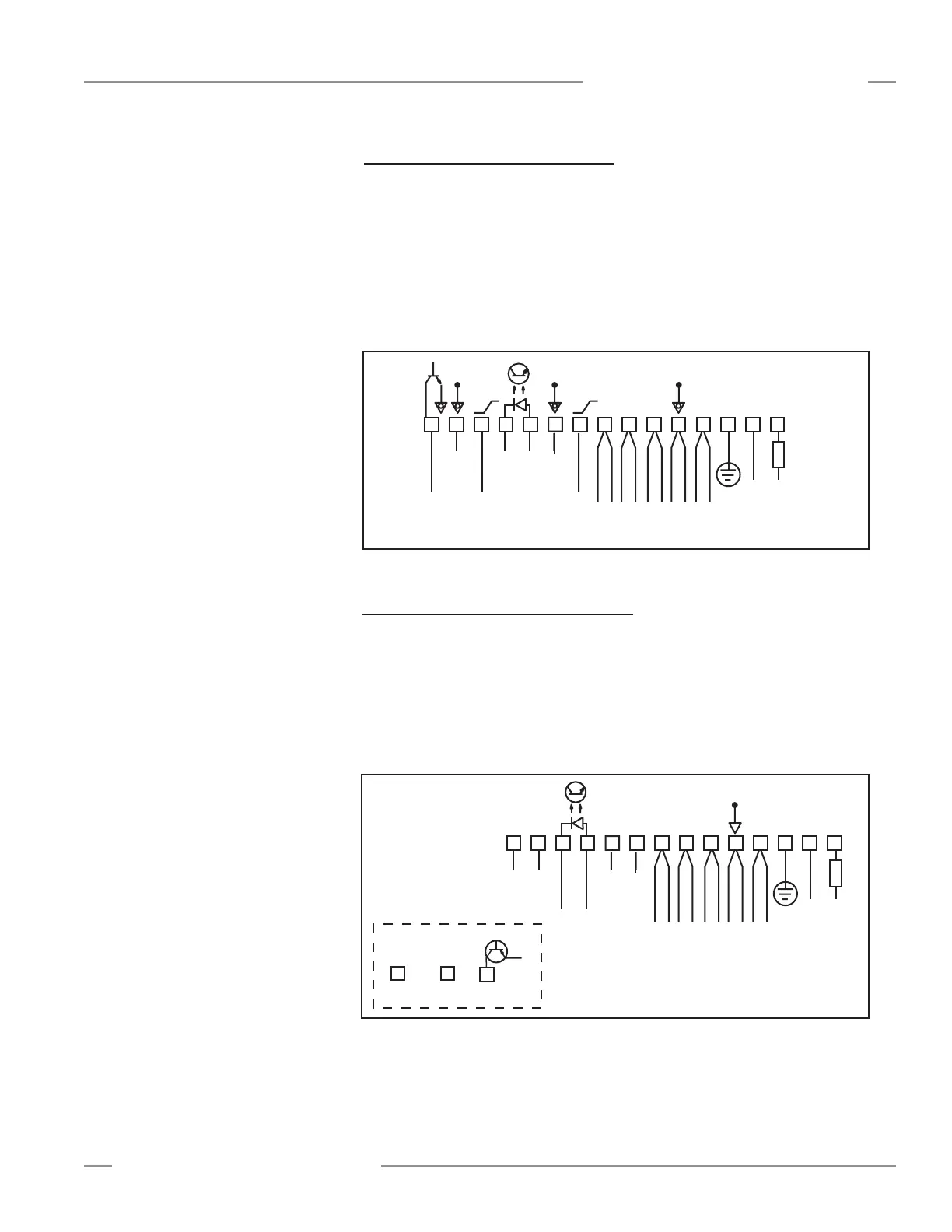
3.4.5 Model MACI-1 Controller Hookup
Current outputs 1 and 2:Controllerterminal#9(Iout1)and#13(Iout2)areanalog
currentoutputs.TheloadforanalogcurrentOutput#1shouldbeconnectedbetween
anexternal16to30Vdcpowersupplyandterminal#9.Theloadforanalogcurrent
Output#2shouldbeconnectedbetweenanexternal16to30Vdcpowersupply
andterminal13.Theloadexternalpowersupplyreturnshouldbecommonwiththe
controllerpowersupplyreturn.Bothoutputsarecurrentsinking.
Alarm:Controllerterminal#15(ALARM)isanopen-collectorNPNtransistorratedat
30Vdcmax.,150mAmax.Itisprotectedagainstoverloadandshortcircuits.
1
+
–
10-30V dc
Gate
16-30V dc
1.2 A Max.
234
5678
9
10131415
F1
BROWN
BLUE
DRAIN (BARE)
BLACK
WHITE
EMITTER and
RECEIVER CABLES
V- V+
30V
150 mA
Max.
ALARM
Power
12 11
Com Com
4-20 mA
I out 2
4-20 mA
I out 1
3.4.6 Model MAC16P-1 Controller Hookup
Terminals#15through#30areopen-collectorPNPtransistoroutputsratedat30V
dcmax.,150mAmax.Theyareprotectedagainstoverloadandshortcircuits.The
isolatedgateinputisatpins11and12.
Controllerterminal#15(output#16)maybeusedasanoutputorasanalarm.
Wheneverthisoutputisactive,theredAlarmLEDisON.
Alloutputsarecurrentsourcing.
Figure 3-9. Model MACI-1 hookup
1
+
–
10-30V dc
Gate
16-30V dc
1.2 A Max.
234
5
678
9
101314
15 30
F1
BROWN
BLUE
DRAIN (BARE)
BLACK
WHITE
EMITTER and
RECEIVER CABLES
V- V+
Power
12 11
NC NC NC NC
through
16 Solid-state Ouputs
V+
150 mA Max each
Figure 3-10. Model MAC16P-1 hookup