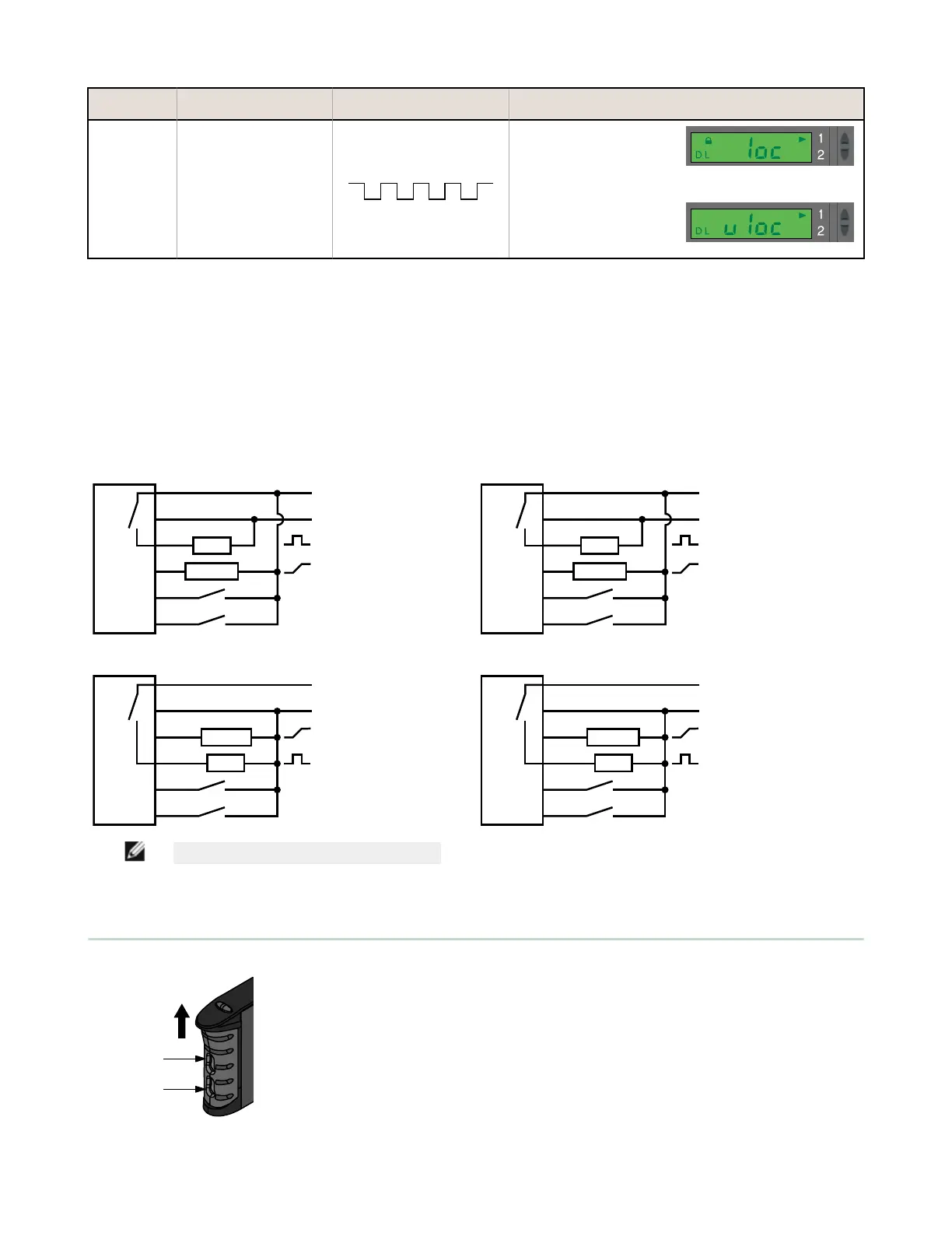
Push Button Remote (0.04 seconds ≤ T ≤ 0.8
seconds)
Result
Enable or
Disable Push
Buttons
Not available with push-button
programming.
From RUN mode, quad-pulse the
remote line to toggle between
selections.
Push buttons Disabled
• Display flashes "loc"
• Padlock icon appears
• Sensor remains in RUN
mode
Push Buttons Enabled
• Display flashes "uloc"
• Padlock icon disappears
• Sensor remains in RUN
mode
Self-Diagnostic Error Modes
In the unlikely event that the setup parameters are lost or become corrupt, the display will continuously scroll: “USEr PSF Error.” Reteach
the sensor to recover. If the problem persists, contact your Banner representative for further information.
Gate Input
The pink wire is configured as a gate input. When this wire is pulled low (e.g., to the sensor ground; 0-0.5 V dc), it inhibits the outputs from
switching, while all other sensor functions continue to be enabled. This feature is useful for controlling when the outputs are allowed to
change states. Gate input function response time is 1 millisecond.
Wiring
NPN, 4-20 mA Output Models
bn
12-24V dc
+
–
1
Teach
Gate
bk
gy
pk
4-20 mA
bu
wh
2
Load
NPN, 0-10V dc Output Models
bn
15-24V dc
+
–
1
Teach
Gate
bk
gy
pk
0-10V dc
bu
wh
2
Load
PNP, 4-20 mA Output Models
bn
12-24V dc
+
–
1
2
Teach
Gate
bu
wh
bk
gy
pk
4-20 mA
Load
PNP, 0-10V dc Output Models
bn
15-24V dc
+
–
1
2
Teach
Gate
bu
wh
bk
gy
pk
0-10V dc
Load
NOTE: QD hookups are functionally identical.
Installation
Install the product on a 35 mm DIN rail or the included mounting bracket.
Plastic Fiber
Emitter Port
Plastic Fiber
Receiver Port
Slides Up to
Release Fibers
D10 Expert
™
- Analog and Discrete Outputs
P/N 65448 Rev. G www.bannerengineering.com - Tel: +1-763-544-3164 13

 Loading...