Manual 2100-669F
Page 10 of 37
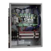
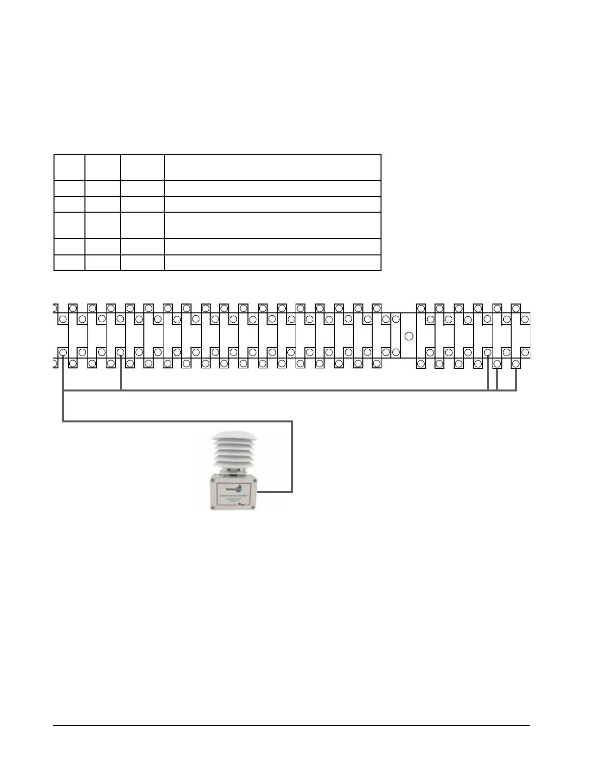
2. Connect the other end of the shielded cable to the sensor terminals. Be sure wires are connected to proper terminals
as shown in table above.
Installing Optional Outdoor Temperature/Humidity Sensor
One optional outdoor temperature/humidity sensor (8301-090) can be installed. Follow the manufacturer's mounting
instructions. Use 18 gauge 5-conductor shielded cable to connect to controller.
FIGURE 7
Remote Outdoor Temperature/Humidity Sensor Installation
1. Connect wires from the 18 gauge shielded cable to terminals #65, #66, #67, #70 and #71.
25
27
29
31
35
33
37
39 4341 45
47 51
49 53
55
59
57
26
28
30 32 34 36
38
40
42 44
46 48
50 52
54
56
58
63
61 65
67
71
69
62
64 66
68
70
72
60
TB#
Wire
Mark
Sensor Description
70 B12 4 Remote Outdoor Temperature Sensor
71 ND 5 Ground
67 B11 1 Remote Outdoor Humidity Sensor: 0-10 VDC
66 GND 3 Ground
65 +VDC 2 +VDC