To Wall-Mount Unit 1
35
37
39 4341 45
47 51
49 53
55
59
57
6
8 10 12
14
16 18
20
22 24
26
28
30
32 34
36
38
40
42 44
46 48
50 52
54
56
58
1
2
3
4
63
61 65
67
71
69
62
64 66
68
70
72
60
–
+
Manual 2100-669F
Page 12 of 37
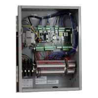
1. Using the field-provided shielded cable, make a small service loop after entering the controller and attach the provided
EMI filter at the intersection of the loop.
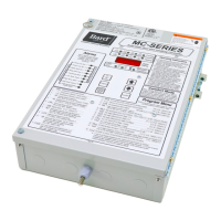
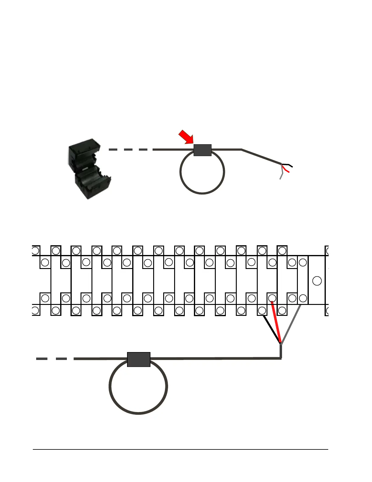
FIGURE 9
Communication Wiring: Termination at the Controller
2. Connect one wire to terminal #56 (negative), the other wire to terminal #57 (positive) and the drain wire to ground
terminal #60.
Communication Wiring
The steps outlined on the following pages show how to connect the communication wiring to the LC controller.
Communication wire connections to the wall-mount unit vary with the different units. See the system installation
instructions included with the wall-mount unit for information on connecting the communication wiring to the wall-
mount unit(s).