BARRETT 900 SERIES TRANSCEIVERS
8.0 Internal options
8.1 Internal scrambler option P/N BCA90031 - available for 940 and 950 transceivers
After removing the jumper JP1 on the RF/Audio PCB, solder the supplied PCB pins into test points
TP9,12,15, and TP24 on the RF/Audio PCB. The optional scrambler PCB is then fitted, the connector on the
scrambler PCB mating with the accessory connector P4 and the PCB pins fitted above mating with the
marked holes. Once in place make sure the scrambler PCB is level and solder the PCB pins to the scrambler
PCB. Note:- the PCB pins from TP9, 12, 15, and TP24 are only used to mechanically secure the scrambler
PCB and make no electrical connection.
The scrambler option is enabled in the setup menu within the transceiver or during programming. Once
enabled the scrambler can be turned off and on by holding down the key labelled "SCRAM". The scrambler
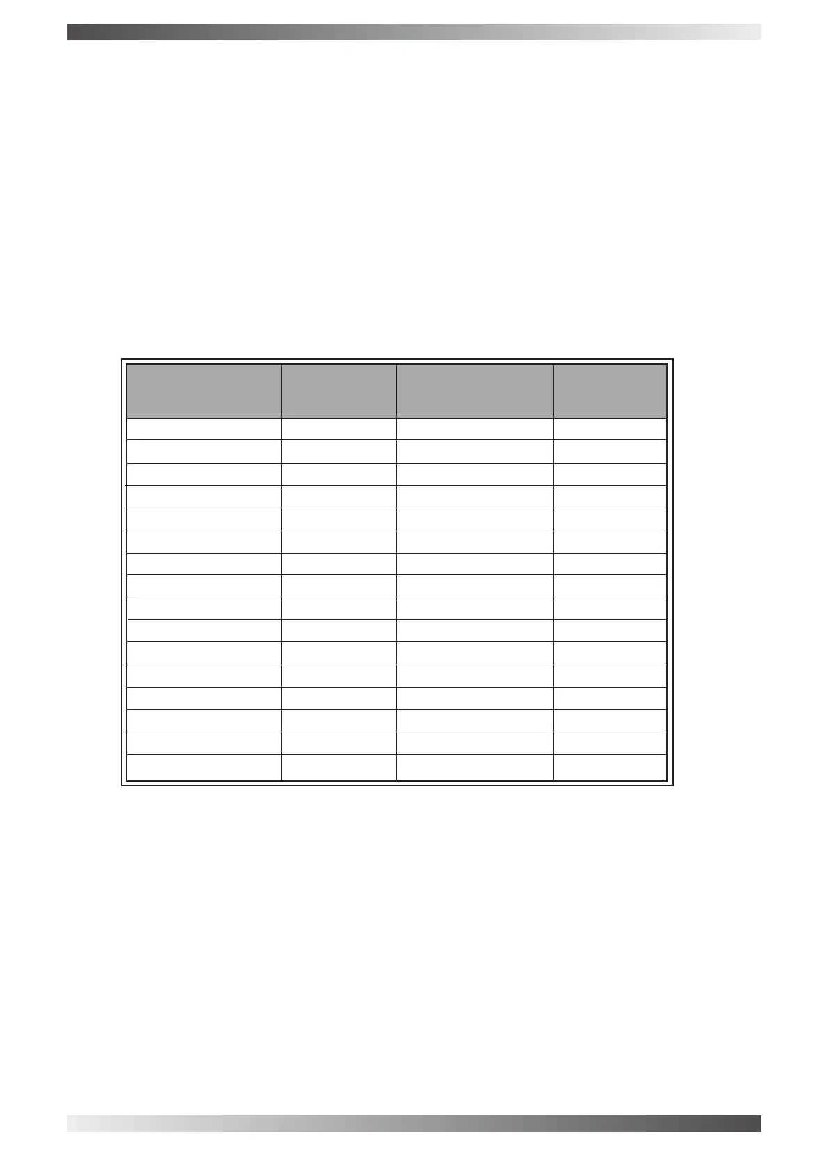
has five Dip switches marked A0, A1, A2, A3 and A4. These allow the scrambling code to be changed as
detailed in the table below. Ensure all transceivers in a net have the same code set to enable reception of
scrambled transmissions.
Note:- a zero means leave the solder link unsoldered, a one means solder the solder link.
Code Number Address Code Number Address
A-A A-A
40 40
0 00000 16 10000
1 00001 17 10001
2 00010 18 10010
3 00011 19 10011
4 00100 20 10100
5 00101 21 10101
6 00110 22 10110
7 00111 23 10111
8 01000 24 11000
9 01001 25 11001
10 01010 26 11010
11 01011 27 11011
12 01100 28 11100
13 01101 29 11101
14 01110 30 11110
15 01111 31 11111
PAGE 46