Handscanners
BCS 3600
ex
series
4 Product description
Subject to technical modifications
17/05/18
33 / 72
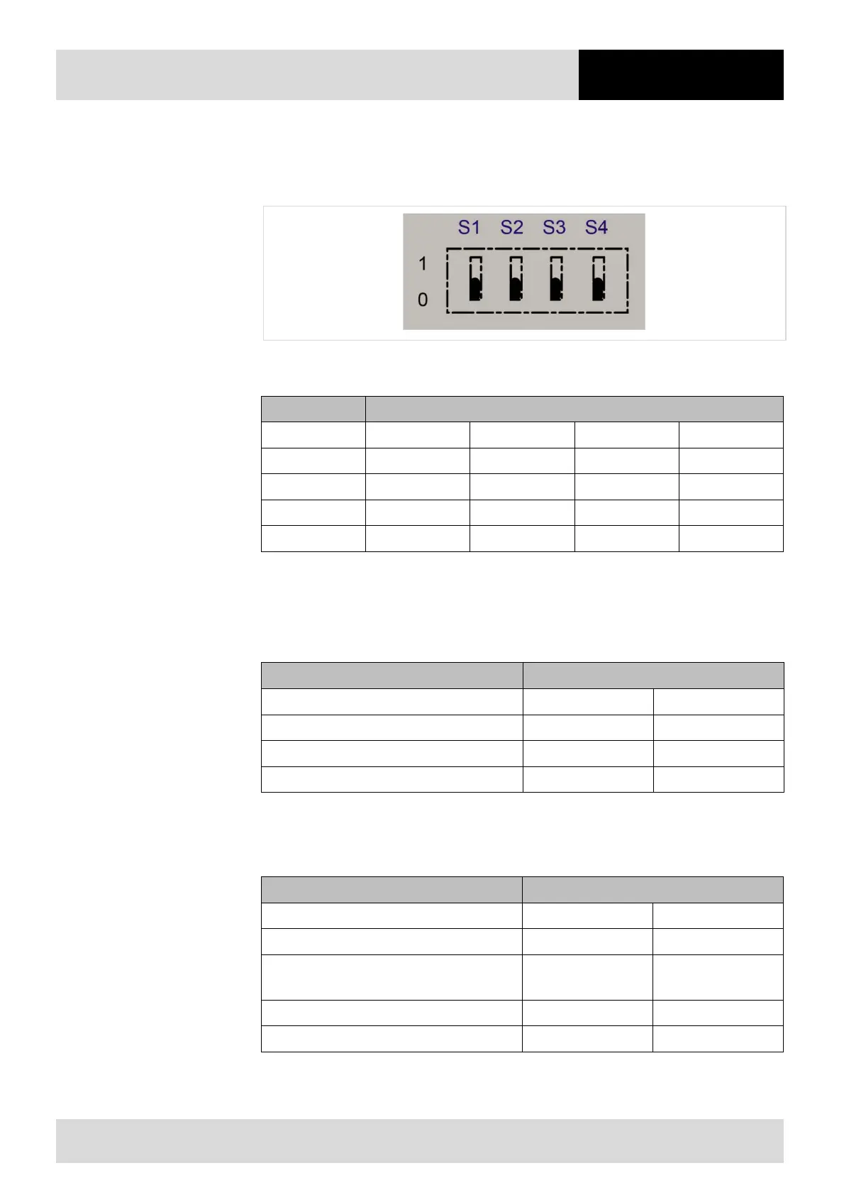
4.6.2 Setting the DIP switches
The DIP switches (X18) must be set as follows depending on the interface used
Fig. 12: DIP switches and switch positions
Setting
Interface S1 S2 S3 S4
RS 232 0 0 0 0
RS 422 0 1 1 0
RS 485 0 0 1 0
USB 1 1 1 0
Tab. 18: Setting
4.6.3 Ranges / maximum cable length of connected cable from the universal supply module to the host or PC
Interface Range
RS 232 20 m / 66 ft 66 ft.
RS 422 1000 m / 3280 ft 3280 ft.
RS 485 1200 m / 3937 ft 3937 ft.
USB 5 m / 16 ft 16 ft.
Tab. 19: Ranges / maximum cable length of connected cable
4.6.4 Permissible core cross-sections
Description of the conductor Permissible core cross-section
Rigid 0.08 mm
2
- 2.5 mm
2
28 – 14 AWG
Flexible 0.08 mm
2
- 2.5 mm
2
28 – 14 AWG
Flexible with wire end ferrule, without plastic
sleeve
0.25 mm
2
- 1.5 mm
2
24 – 16 AWG
Flexible with wire end ferrule, with plastic sleeve
0.25 mm
2
- 1.5 mm
2
24 – 16 AWG
Wire diameter (AWG) 28 - 12 kcmil 36 – 39 AWG
Tab. 20: Permissible core cross sections