9424200996 41-1
BE1-11m Trip Circuit Monitor (52TCM)
41 • Trip Circuit Monitor (52TCM)
A trip circuit monitor (52TCM) element continually monitors the circuit breaker trip circuit for voltage and
continuity.
Element logic connections are made on the BESTlogic™Plus screen in BESTCOMSPlus® and element
operational settings are configured on the Trip Circuit Monitor (52TCM) settings screen in
BESTCOMSPlus. A summary of the logic output and operational settings appears at the end of this
chapter.
Element Operation
A closed breaker with no voltage detected across the trip contacts can indicate that a trip circuit fuse is
open or there is a loss of continuity in the trip coil circuit. The 52TCM element detects this condition and
signals an alarm. In BESTlogicPlus, the Alarm output can be connected to other logic elements or a
physical relay output to annunciate the condition and initiate corrective action.
Breaker Status
Breaker status (open or closed) is obtained through the breaker status reporting function (configured by
the Breaker Status logic block). Refer to the Breaker Monitoring chapter for more information.
Programmable Alarm
A 52 Trip Coil Monitor alarm occurs when the breaker status reporting function detects a closed breaker
and no trip circuit voltage for the duration of a 500 millisecond coordination delay. The alarm appears on
the front-panel display, web page interface, and on the Alarms metering screen in BESTCOMSPlus.
Refer to the Alarms chapter for information on how to program alarms.
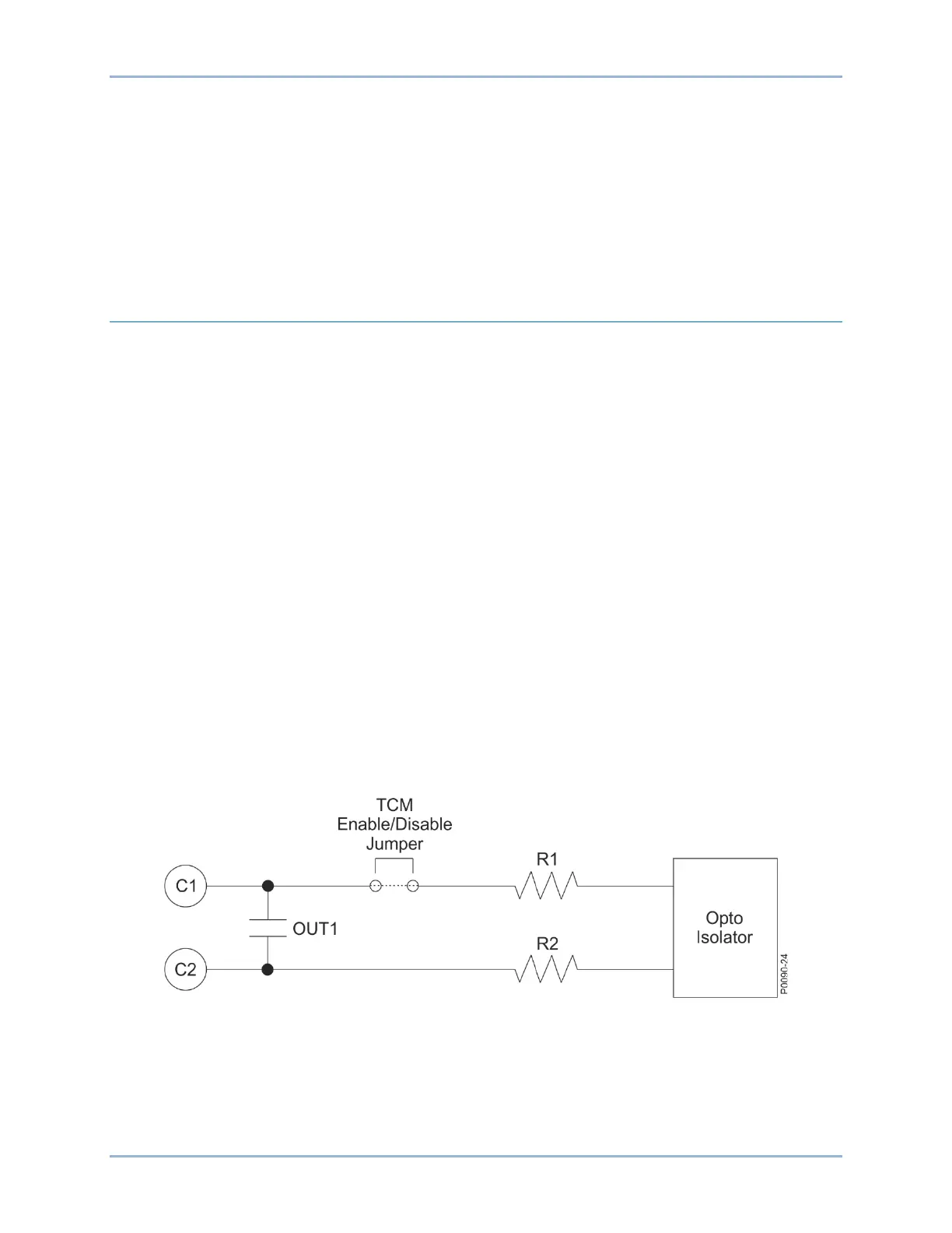
Detector Circuit
The detector circuit used by the 52TCM element is placed in parallel with the OUT1 contact when the
TCM jumper is installed. This contact is used in all of the preprogrammed logic schemes as the main trip
output. The detector circuit across OUT1 is not polarity sensitive because the optical isolator used for
detecting continuity is connected across a full wave bridge. See Figure 41-1.
The amount of current drawn through the optical isolator circuit depends on the total input impedance for
each power supply voltage rating (see Table 41-1).
Figure 41-1. Trip Detector Circuit