9424200996 4-1
BE1-11m Contact Inputs and Outputs
4 • Contact Inputs and Outputs
BE1-11m Motor Protection Systems provide seven contact inputs, eight general-purpose contact outputs,
and one dedicated fail-safe alarm contact output. Each input and output is isolated and terminated at
separate terminals. This section describes the function and setup of each input and output.
Contact-Sensing Inputs
Either seven or 10 contact inputs are available to initiate BE1-11m protection system actions. Refer to the
style chart for I/O options. Each isolated input requires an external wetting voltage. The nominal
voltage(s) of the external dc source(s) must fall within the BE1-11m dc power supply input voltage range.
To enhance user flexibility, the BE1-11m protection system uses wide-range ac/dc power supplies that
cover several common control voltage ratings. To enhance flexibility, the input circuits are designed to
respond to voltages at the lower end of the control voltage range while not overheating at the high end of
the control voltage range.
The contact input circuits are polarity sensitive. When an ac wetting voltage is applied, the input signal is
half-wave rectified by the opto-isolator diodes. The contact inputs drive BESTlogic™Plus variables IN1
through IN10. Each contact input is completely programmable so meaningful labels can be assigned to
each input and the logic-high and logic-low states. The BESTlogicPlus chapter provides more information
about using contact inputs in your programmable logic scheme.
Contact-Sensing Input Jumpers
The BE1-11m protection system is delivered with the jumpers in the
HIGH position. Read the following paragraphs before placing the BE1-
11m in service.
Energizing levels for the contact-sensing inputs are jumper selectable for a minimum of approximately
5 Vdc for 24 Vdc nominal sensing voltages, 26 Vdc for 48 Vdc nominal sensing voltages, or 69 Vdc for
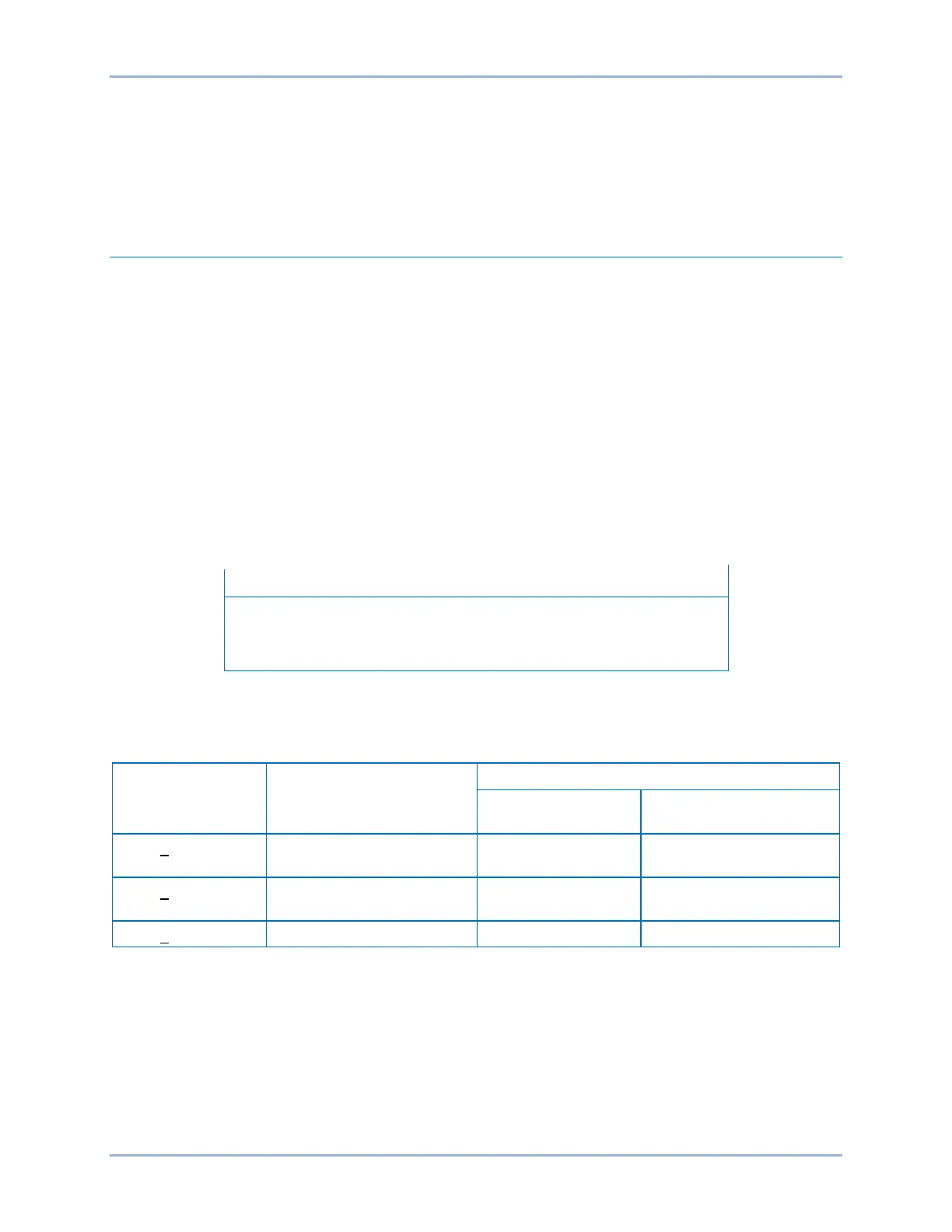
125 Vdc nominal sensing voltages. See Table 4-1 for the contact-sensing turn-on voltages.
Table 4-1. Contact-Sensing Turn-On Voltages
Style Option Nominal Input Voltage
Contact Sensing Turn-On Voltage *
Jumper Installed
(Low Position)
Jumper Not Installed
(High Position)
69 to 100 Vdc
56 to 97 Vac
69 to 100 Vdc
56 to 97 Vac
138 to 200 Vdc
112 to 194 Vac
* AC voltage ranges are calculated using the default recognition time (4 ms) and debounce time (16 ms).
Each BE1-11m is delivered with the contact-sensing jumpers disconnected for operation in the higher end
of the control voltage range. If the contact-sensing inputs are to be operated at the lower end of the
control voltage range, the jumpers must be installed.
The following paragraphs describe how to locate and remove/change the contact-sensing input jumpers:
1. Remove the BE1-11m from service and de-energize it.
2. The contact-sensing input jumpers are located behind the rear terminal blocks that are used for
input connections. Using a 7/64” hex tool, remove the rear terminal block(s) associated with the