4-2 9424200996
Contact Inputs and Outputs BE1-11m
input(s) that you want to configure. Observe all electrostatic discharge (ESD) precautions when
handling the BE1-11m.
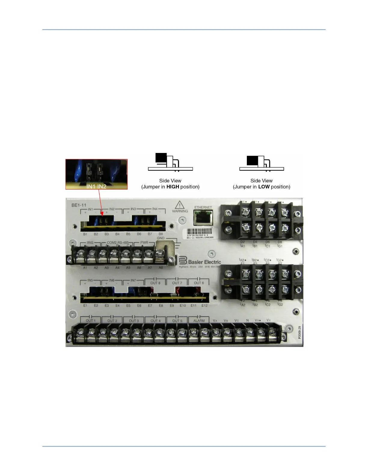
3. Using the input labels on the rear panel as a guide, locate the appropriate jumper terminal block
that is mounted on the circuit board. Each terminal block has two sets of pins. With the jumper as
installed at the factory, one pin should be visible when viewed from the back of the unit. This
configuration allows the inputs to operate at the higher end of the control voltage range. Figure
4-1 illustrates the location of the contact-sensing jumpers. The jumpers are shown in the HIGH
position.
4. To select operation at the lower end of the control voltage range, install the jumper across the two
pins using needle-nose pliers. Use care when removing and installing each jumper so that no
components are damaged.
5. When all jumpers are positioned for operation in the desired control voltage range, reinstall the
rear terminal block(s).
6. Using a 7/64” hex tool, tighten the screws to 10 in-lbs (1.12 N•m).
Figure 4-1. Contact-Sensing Jumper Locations (Standard I/O Option)
Digital Input Conditioning Function
Status of the contact-sensing inputs is checked every 1 millisecond. User-settable digital contact
recognition and debounce timers condition the signals applied to the inputs. These parameters can be
adjusted to obtain the optimum compromise between speed and security for a specific application. (See
Figure 4-2.)
If the sampled status of a monitored contact is detected as energized for the recognition time, the logic
variable changes from a de-energized (logic 0 or false) state to an energized (logic 1 or true) state. Once
contact closure is recognized, the logic variable remains in the energized state until the sampled status of
the monitored contact is detected to be de-energized for a period that is longer than the debounce time.