9424200996 27-1
BE1-11m Lockout Functions (86)
27 • Lockout Functions (86)
Two lockout function (86) elements can be used to prevent operation of circuit breakers or other devices
until the condition causing lockout is eliminated.
The two, identical lockout function elements are designated 86-1 and 86-2. Element logic connections are
made on the BESTlogicPlus screen in BESTCOMSPlus and element operational settings are configured
on the Lockout Functions screen in BESTCOMSPlus. A summary of the logic inputs and outputs and
operational settings appears at the end of this chapter.
BESTCOMSPlus Navigation Path: Settings Explorer, Control, Lockout Functions (86)
HMI Navigation Path: Settings Explorer, Control, Lockout 86
Element Operation
When the Set input is asserted, the output of the function becomes true (breaker opens). When the Reset
input is asserted, the output becomes false (breaker closes). If both inputs are asserted at the same time,
the Set input will have priority and drive the output to true. The state of the function is stored in nonvolatile
memory.
Logic Connections
Lockout function element logic connections are made on the BESTlogicPlus screen in BESTCOMSPlus.
The lockout function element logic block is illustrated in Figure 27-1. Logic inputs and outputs are
summarized in Table 27-1.
Figure 27-1. Lockout Function Element Logic Block
Table 27-1. Logic Inputs and Outputs
Sets the state of the output to true
Sets the state of the output to false
True when the Set input is asserted
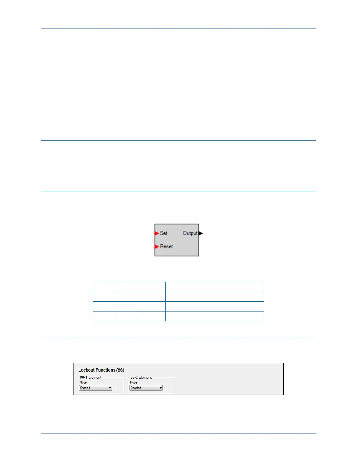
Operational Settings
Lockout function element operational settings are configured on the Lockout Functions (86) settings
screen (Figure 27-2) in BESTCOMSPlus.
Figure 27-2. Lockout Functions Settings Screen